ГОЛОВКА БЛОКА ЦИЛИНДРОВ ПОВТОРНАЯ СБОРКА
-
INSTALL TIGHT PLUG
Note
If water leaks from the tight plug or the plug, or the plug corrodes, replace it.
-
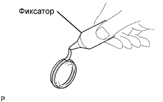
Apply adhesive to a new tight plug.
Adhesive Toyota Genuine Adhesive 1324, Three Bond 1324 or equivalent -
Using SST and a hammer, tap in the tight plug as shown in the illustration.
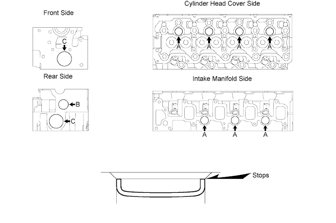
Position A
- SST
- 09950-60010 ( 09951-00250 )
- 09950-70010 ( 09951-07100 )
Position B
- SST
- 09950-60010 ( 09951-00300 )
- 09950-70010 ( 09951-07100 )
Position C
- SST
- 09950-60010 ( 09951-00450 )
- 09950-70010 ( 09951-07100 )
-
-
INSTALL STUD BOLT
Note
If the stud bolt is deformed or the threads are damaged, replace it.
-
Install the stud bolts as shown in the illustration.
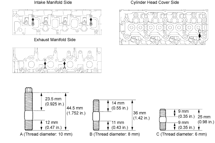
- Torque:
- 26 N*m { 265 kgf*cm, 19 ft.*lbf, for bolt A }
- 12 N*m { 120 kgf*cm, 9 ft.*lbf, for bolt B }
- 6.0 N*m { 60 kgf*cm, 53 in.*lbf, for bolt C }
-
-
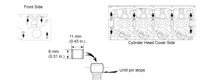
INSTALL RING PIN
Note
It is not necessary to remove the ring pin unless it is being replaced.
-
Using a plastic hammer, tap in a new ring pin until it stops.
-
-
INSTALL SEMICIRCULAR PLUG
-
Remove any old packing (FIPG) material.
-
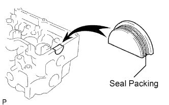
Apply seal packing to the semicircular plug as shown in the illustration.
Seal packing Toyota Genuine Seal Packing Black, Three Bond 1207B or equivalent Note
-
The semicircular plug must be installed within 3 minute from the completion of applying the seal packing.
-
Prevent FIPG from being stuck to the camshaft thrust groove.
-
-
Install the semicircular plug to the cylinder head.
-
-
INSTALL COMBUSTION CHAMBER SUB-ASSEMBLY
-
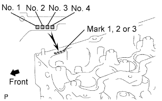
Select the number of shim, depending on the table below.
Select the number of shim Number Mark of Cylinder Head Number of Shim 1 0 2 0 1 3 1 2 Shim thickness 0.03 mm (0.0012 in.) -
Align the combustion chamber knock pin with the cylinder head notch.
-
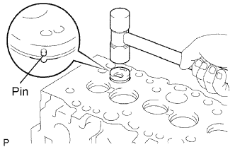
Using a plastic-faced hammer, tap in the combustion chamber.
-
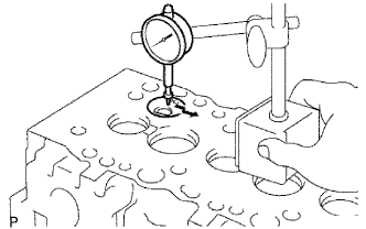
Using a dial indicator, check the combustion chamber protrusion.
Combustion chamber protrusion Minus 0.03 to Plus 0.03 mm (Minus 0.0012 to Plus 0.0012 in.) If the protrusion is less than the specified, adjust with shims.
If the protrusion is greater than the specified, replace the chamber and recheck the protrusion.
-
-
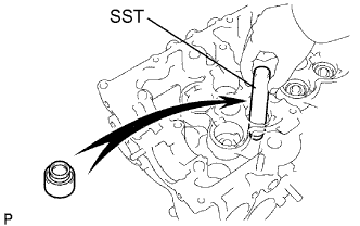
INSTALL VALVE STEM OIL SEAL
-
Using SST, push in a new oil seal.
- SST
- 09201-41020
-
-
INSTALL INTAKE VALVE
-
Install the valve, spring seat plate washer, valve spring and spring retainer.
-
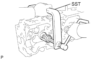
Using SST, compress the valve spring and place the 2 retainer locks around the valve stem.
- SST
- 09202-70020 ( 09202-00030 )
-
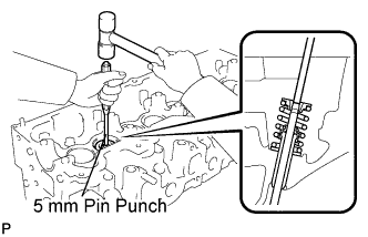
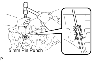
Using a 5 mm pin punch and plastic-faced hammer, lightly tap the valve stem tip to ensure a proper fit.
Note
Be careful not to damage the valve stem tip.
-
-
INSTALL EXHAUST VALVE
-
Install the valve, spring seat, valve spring and spring retainer.
-
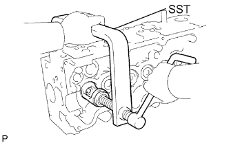
Using SST, compress the valve spring and place the 2 retainer locks around the valve stem.
- SST
- 09202-70020 ( 09202-00030 )
-
Using a 5 mm pin punch and plastic-faced hammer, lightly tap the valve stem tip to ensure a proper fit.
Note
Be careful not to damage the valve stem tip.
-
-
INSTALL VALVE LIFTER
-
Install the valve lifter and shim.
-
Check that the valve lifter rotates smoothly by hand.
-