AUTOMATIC HIGH BEAM SYSTEM TERMINALS OF ECU
-
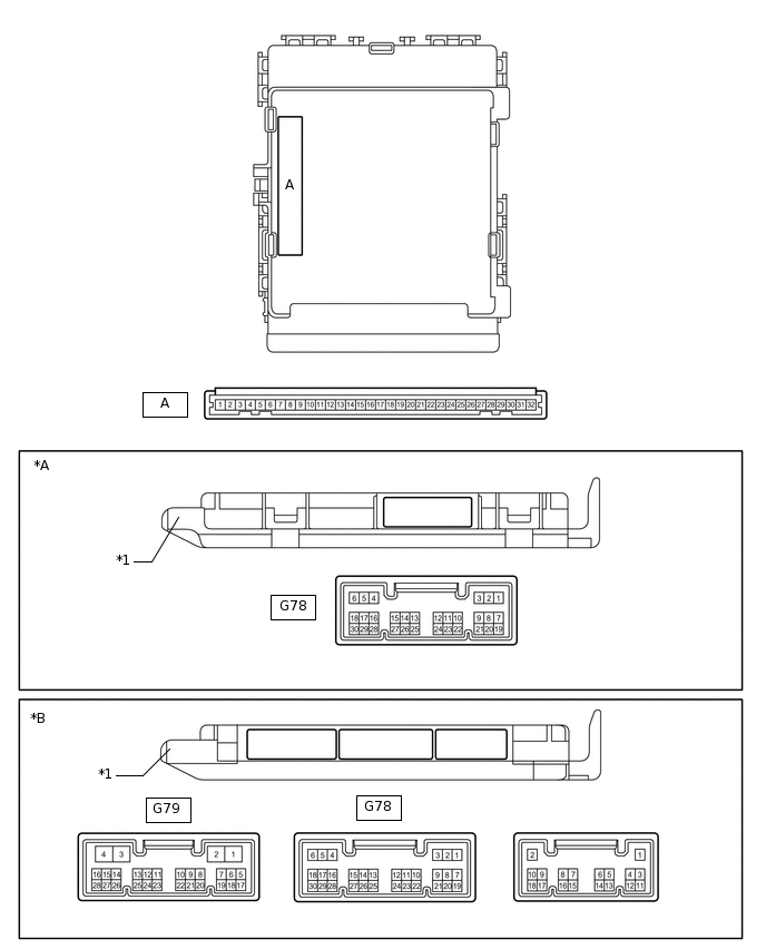
*A
Main Body ECU (Multiplex Network Body ECU) with 1 connector
*B
Main Body ECU (Multiplex Network Body ECU) with 3 connectors
*1
Main Body ECU (Multiplex Network Body ECU)
-
-
CHECK INSTRUMENT PANEL JUNCTION BLOCK ASSEMBLY, MAIN BODY ECU (MULTIPLEX NETWORK BODY ECU)
Remove the main body ECU (multiplex network body ECU) from the instrument panel junction block assembly.
Connect the instrument panel junction block assembly connectors.
Measure the voltage and resistance according to the value(s) in the table below.
Terminal No. (Symbol)
Wiring Color
Terminal Description
Condition
Specified Condition
A-32 (IG) - Body ground
-
Ignition power supply
Ignition switch ON
11 to 14 V*1
10.5 to 14 V*2
Ignition switch off
Below 1 V
A-30 (BECU) - Body ground
-
Battery power supply
Always
11 to 14 V
A-29 (ACC) - Body ground
-
ACC power supply
Ignition switch ACC
11 to 14 V
Ignition switch off
Below 1 V
A-11 (GND1) - Body ground
-
Ground
Always
Below 1 Ω
*1: w/o Stop and Start System
*2: w/ Stop and Start System
If the result is not as specified, there may be a malfunction in the wire harness or instrument panel junction block assembly.
Install the main body ECU (multiplex network body ECU).
Measure the voltage and pulse according to the value(s) in the table below.
Terminal No. (Symbol)
Wiring Color
Terminal Description
Condition
Specified Condition
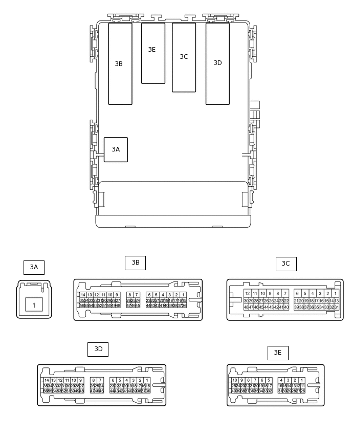
3B-54 (DIM) - Body ground
LG - Body ground
DIMMER relay drive output
Headlight dimmer switch in high or high flash position
Below 1 V
Headlight dimmer switch not in high or high flash position
11 to 14 V
G78-5 (HU) - Body ground
Y - Body ground
Headlight dimmer switch high signal input
Headlight dimmer switch in high position
Below 1 V
Headlight dimmer switch in low position
Pulse generation*1
11 to 14 V*2
G78-20 (CLTB) - G78-22 (CLTE)
W - V
Automatic light control sensor power supply output
Ignition switch off
Below 1 V
Ignition switch ON
Headlight dimmer switch in AUTO position
11 to 14 V
G78-21 (CLTS) - Body ground
G - Body ground
Automatic light control sensor signal input
Ignition switch off
Below 1 V
Ignition switch ON
Headlight dimmer switch in AUTO position
Automatic light control sensor covered with a hand → Automatic light control sensor exposed to ambient light
Pulse generation (See waveform 1)
G78-28 (A) - Body ground
G - Body ground
Headlight dimmer switch AUTO position signal input
Headlight dimmer switch in AUTO position
Below 1 V
Headlight dimmer switch not in AUTO position
Pulse generation*1
11 to 14 V*2
*1: Main Body ECU (multiplex network body ECU) with 3 Connectors
*2: Main Body ECU (multiplex network body ECU) with 1 Connectors
-
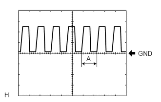
Waveform 1
Item
Content
Terminal No. (Symbol)
G78-21 (CLTS) - Body ground
Tool setting
5 V/DIV., 5 ms./DIV.
Condition
Ignition switch ON
Headlight dimmer switch in AUTO position
Automatic light control sensor covered with a hand → Automatic light control sensor exposed to ambient light
Tip:If the ambient light becomes brighter, width A becomes narrower.
-
CHECK LANE DEPARTURE WARNING CAMERA
Check the lane departure warning camera.