БЛОК ДВИГАТЕЛЯ ПРОВЕРКА
-
INSPECT CAMSHAFT (for Bank 1)
-
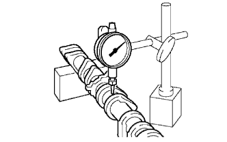
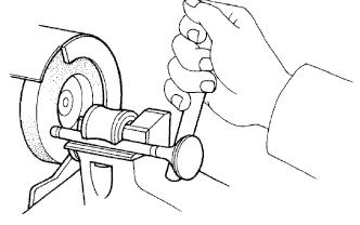
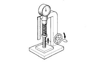
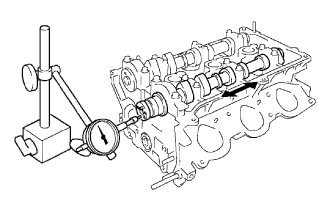
Inspect the camshaft for runout.
-
Place the camshaft on V-blocks.
-
Using a dial indicator, measure the circle runout at the center journal.
Maximum circle runout 0.06 mm (0.0024 in.) If the circle runout is greater than the maximum, replace the camshaft.
-
-
Inspect the cam lobes.
-
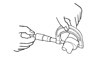
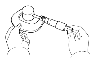
Using a micrometer, measure the cam lobe height.
Standard cam lobe height Camshaft Cam lobe height Intake 44.168 to 44.268 mm (1.7389 to 1.7428 in.) Exhaust 44.580 to 44.680 mm (1.7551 to 1.7591 in.) Minimum cam lobe height Camshaft Cam lobe height Intake 44.018 mm (1.7330 in.) Exhaust 44.430 mm (1.7492 in.) If the cam lobe height is less than the minimum, replace the camshaft.
-
-
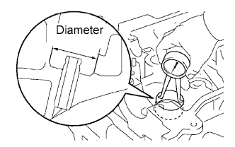
Inspect the camshaft journals.
-
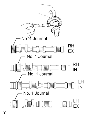
Using a micrometer, measure the journal diameter.
Standard journal diameter Journal Diameter No. 1 journal 35.971 to 35.985 mm (1.4162 to 1.4167 in.) Other journal 22.959 to 22.975 mm (0.9039 to 0.9045 in.) If the journal diameter is not as specified, check the oil clearance.
-
-
-
INSPECT CAMSHAFT TIMING GEAR (for Bank 1)
-
Fix the intake camshaft with a vise.
Note
Be careful not to damage the camshaft.
-
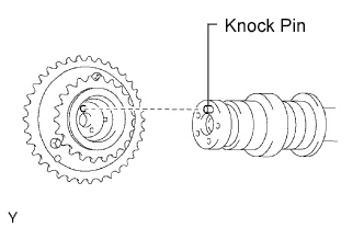
Align the knock pin hole in the camshaft timing gear assembly with the knock pin of the camshaft, and install the camshaft timing gear assembly with the bolt.
- Torque:
- 100 N*m { 1,020 kgf*cm, 74 ft.*lbf }
-
Confirm the camshaft timing gear assembly is locked.
-
Release the lock pin.
-
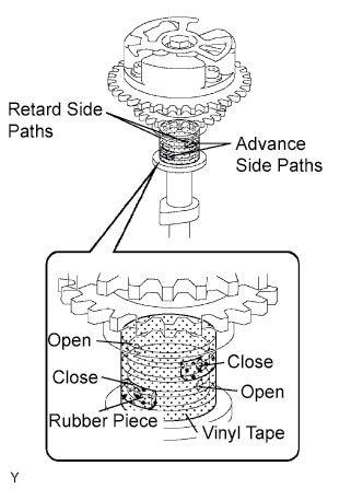
Cover 4 oil paths of cam journal with vinyl tape as shown in the illustration.
Tech Tips
The 4 oil paths are provided in the groove of the camshaft. Plug two of the paths with rubber pieces.
-
Break through the tapes of the advance side path and the retard side path on the opposite side of the groove.
-
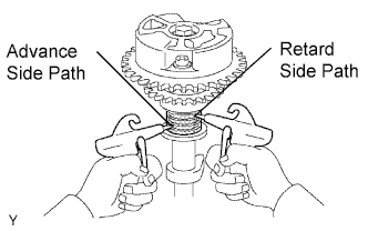
Put air pressure into 2 broken paths (the advance side path and the retard side path) with about 200 kPa (2.0 kgf/cm2, 28 psi).
Note
Cover the paths with cloth or equipment to avoid oil splashing.
-
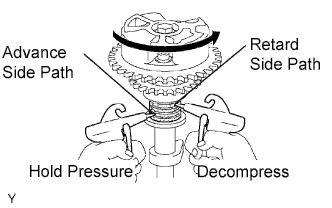
Confirm if the camshaft timing gear assembly rotates in the timing advance direction when weakening the air pressure of the timing retard path.
Tech Tips
The lock pin is released, and camshaft timing gear, rotates in the advance direction.
-
When the camshaft timing gear comes to the most advanced position, take out the air pressure of the timing retard side path, and then, take out that of timing advance side path.
Note
Camshaft timing assembly gear occasionally shifts to the retard side abruptly, if the air compression of the advanced side path is released before retard side path. It often results the breakage of the lock pin.
-
-
Check the smooth revolution.
-
Except the position where the lock pin meets at the most retard angle, let the camshaft timing gear assembly turn back and forth and check the movable range and that there is no disturbance.
Standard Movable range is about 31°. Note
Be sure to perform this check by hand, instead of air pressure.
-
-
Check the lock in the most retarded position.
-
Confirm that the camshaft timing gear assembly is locked at the most retarded position.
-
-
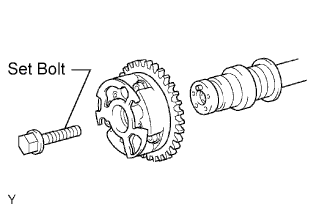
Remove the set bolt and camshaft timing gear assembly.
Note
Be sure not to remove the other 3 bolts.
-
-
INSPECT CAMSHAFT (for Bank 2)
-
Inspect the camshaft for runout.
-
Place the camshaft on V-blocks.
-
Using a dial indicator, measure the circle runout at the center journal.
Maximum circle runout 0.06 mm (0.0024 in.) If the circle runout is greater than the maximum, replace the camshaft.
-
-
Inspect the cam lobes.
-
Using a micrometer, measure the cam lobe height.
Standard cam lobe height Camshaft Cam lobe height Intake 44.168 to 44.268 mm (1.7389 to 1.7428 in.) Exhaust 44.580 to 44.680 mm (1.7551 to 1.7591 in.) Minimum cam lobe height Camshaft Cam lobe height Intake 44.018 mm (1.7330 in.) Exhaust 44.430 mm (1.7492 in.) If the cam lobe height is less than the minimum, replace the camshaft.
-
-
Inspect the camshaft journals.
-
Using a micrometer, measure the journal diameter.
Standard journal diameter Journal Diameter No. 1 journal 35.971 to 35.985 mm (1.4162 to 1.4167 in.) Other journal 22.959 to 22.975 mm (0.9039 to 0.9045 in.) If the journal diameter is not as specified, check the oil clearance.
-
-
-
INSPECT CAMSHAFT TIMING GEAR (for Bank 2)
-
Fix the intake camshaft with a vise.
Note
Be careful not to damage the camshaft.
-
Align the knock pin hole in the camshaft timing gear assembly with the knock pin of the camshaft, and install the camshaft timing gear assembly with the bolt.
- Torque:
- 100 N*m { 1,020 kgf*cm, 74 ft.*lbf }
-
Confirm the camshaft timing gear assembly is locked.
-
Release the lock pin.
-
Cover 4 oil paths of cam journal with vinyl tape as shown in the illustration.
Tech Tips
The 4 oil paths are provided in the groove of the camshaft. Plug two of the paths with rubber pieces.
-
Break through the tapes of the advance side path and the retard side path on the opposite side of the groove.
-
Put air pressure into 2 broken paths (the advance side path and the retard side path) with about 200 kPa (2.0 kgf/cm2, 28 psi).
Note
Cover the paths with cloth or equipment to avoid oil splashing.
-
Confirm if the camshaft timing gear assembly rotates in the timing advance direction when weakening the air pressure of the timing retard path.
Tech Tips
The lock pin is released, and camshaft timing gear, rotates in the advance direction.
-
When the camshaft timing gear comes to the most advanced position, take out the air pressure of the timing retard side path, and then take out that of timing advance side path.
Note
Camshaft timing assembly gear occasionally shifts to the retard side abruptly, if the air compression of the advanced side path is released before retard side path. It often results the breakage of the lock pin.
-
-
Check the smooth revolution.
-
Except the position where the lock pin meets at the most retard angle, let the camshaft timing gear assembly turn back and forth and check the movable range and that there is no disturbance.
Standard Movable range is about 31° and gear moves smoothly. Note
Be sure to perform this check by hand, instead of air pressure.
-
-
Check the lock in the most retarded position.
-
Confirm that the camshaft timing gear assembly is locked at the most retarded position.
-
-
Remove the set bolt and camshaft timing gear assembly.
Note
Be sure not to remove the other 3 bolts.
-
-
INSPECT CYLINDER HEAD SET BOLT
-
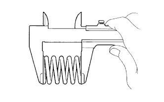
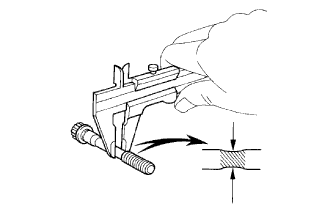
Using a vernier caliper, measure the thread outside diameter of the bolt.
Standard outside diameter 10.85 to 11.00 mm (0.4272 to 0.4331 in.) Minimum outside diameter 10.7 mm (0.421 in.) If the diameter is less than the minimum, replace the bolt.
-
-
INSPECT CHAIN
-
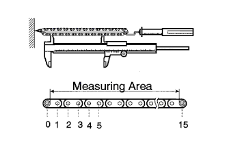
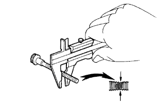
Using a spring scale, pull the chain with 147 N (15.0 kgf, 33.1 lbf). Using a vernier caliper, measure the length of 15 links of the chain.
Maximum chain elongation 146.8 mm (5.780 in.) Note
Make the same measurements pulling at 3 or more places selected at random, and average the length.
If the elongation is greater than the maximum, replace the chain.
-
-
INSPECT NO. 2 CHAIN
-
Using a spring scale, pull the chain with 147 N (15.0 kgf, 33.1 lbf). Using a vernier caliper, measure the length of 15 links of the chain.
Maximum chain elongation 146.8 mm (5.780 in.) Note
Make the same measurements pulling at 3 or more places selected at random, and average the length.
If the elongation is greater than the maximum, replace the chain.
-
-
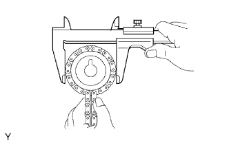
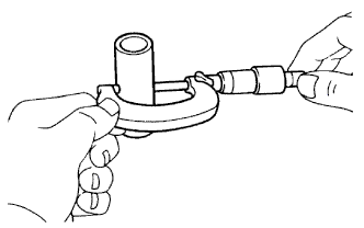
INSPECT CAMSHAFT TIMING GEAR
-
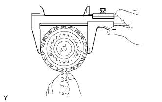
Wrap the No. 1 chain around the larger gear of camshaft timing gear assembly.
-
Using a vernier caliper, measure the timing gear with the chain.
Minimum gear diameter with chain 115.5 mm (4.547 in.) Note
Vernier calipers must contact the chain rollers for the measuring.
If the diameter is less than the minimum, replace the No. 1 chain and camshaft timing gear assembly.
-
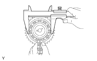
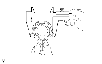
Wrap the No. 2 chain around the smaller gear of camshaft timing gear assembly.
-
Using a vernier caliper, measure the timing gear with the chain.
Minimum gear diameter with chain 73.1 mm (2.878 in.) Note
Vernier calipers must contact the chain rollers for the measuring.
If the diameter is less than the minimum, replace the No. 2 chain and camshaft timing gear assembly.
-
-
INSPECT CAMSHAFT TIMING SPROCKET
-
Wrap the No. 2 chain around the camshaft timing gear.
-
Using a vernier caliper, measure the camshaft timing gear diameter with the chain .
Minimum gear diameter with chain 73.1 mm (2.878 in.) Note
Vernier calipers must contact the chain rollers for the measuring.
If the diameter is less than the minimum, replace the No. 2 chain and the camshaft timing gear.
-
-
INSPECT CRANKSHAFT TIMING SPROCKET
-
Wrap the No. 1 chain around the crankshaft timing gear.
-
Using a vernier caliper, measure the crankshaft timing gear diameter with the chain.
Minimum gear diameter with chain 61.0 mm (2.402 in.) Note
Vernier calipers must contact the chain rollers for the measuring.
If the diameter is less than the minimum, replace the No. 1 chain and crankshaft timing gear.
-
-
INSPECT NO. 1 IDLE GEAR
-
Wrap the No. 1 chain around the idle gear.
-
Using a vernier caliper, measure the idle gear with the chain.
Minimum gear diameter with chain 61.0 mm (2.402 in.) Note
Vernier calipers must contact the chain rollers for the measuring.
If the diameter is less than the minimum, replace the No. 1 chain and idle gear.
-
-
INSPECT IDLE GEAR SHAFT OIL CLEARANCE
-
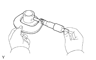
Using a micrometer, measure the idle gear shaft diameter.
Idle gear shaft diameter 22.987 to 23.000 mm (0.9050 to 0.9055 in.) -
Using a caliper gauge, measure the inside diameter of the idle gear.
Idle gear inside diameter 23.02 to 23.03 mm (0.9063 to 0.9067 in.) -
Subtract the idle gear shaft diameter measurement from the idle gear inside diameter measurement.
Standard oil clearance 0.020 to 0.043 mm (0.0008 to 0.0017 in.) Maximum oil clearance 0.093 mm (0.0037 in.)
-
-
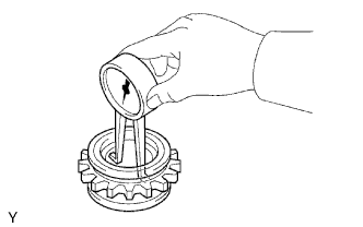
INSPECT NO. 1 CHAIN TENSIONER
-
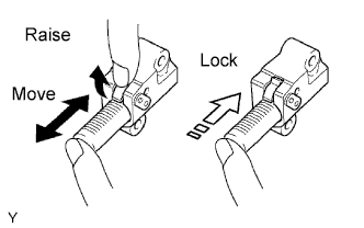
Check that the plunger moves smoothly when the ratchet pawl is raised with finger.
-
Release the ratchet pawl and check that the plunger is locked in place by the ratchet pawl and does not move when pushed with finger.
-
-
INSPECT NO. 2 CHAIN TENSIONER
-
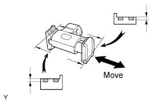
Check that the plunger moves smoothly.
-
Measure the worn depth of the chain tensioner slipper.
Maximum depth 1.0 mm (0.039 in.) If the depth is greater than the maximum, replace the No. 2 chain tensioner.
-
-
INSPECT NO. 3 CHAIN TENSIONER
-
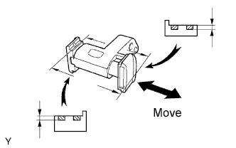
Check that the plunger moves smoothly.
-
Measure the worn depth of the chain tensioner slipper.
Maximum depth 1.0 mm (0.039 in.) If the depth is greater than the maximum, replace the No. 3 chain tensioner.
-
-
INSPECT CHAIN TENSIONER SLIPPER
-
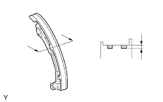
Measure the worn depth of the chain tensioner slipper.
Maximum depth 1.0 mm (0.039 in.) If the depth is greater than the maximum, replace the chain tensioner slipper.
-
-
INSPECT NO. 1 CHAIN VIBRATION DAMPER
-
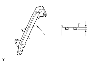
Measure the worn depth of the No. 1 chain vibration damper.
Maximum depth 1.0 mm (0.039 in.) If the depth is greater than the maximum, replace the No. 1 chain vibration damper.
-
-
INSPECT NO. 2 CHAIN VIBRATION DAMPER
-
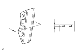
Measure the worn depth of the No. 2 chain vibration damper.
Maximum depth 1.0 mm (0.039 in.) If the depth is greater than the maximum, replace the No. 2 chain vibration damper.
-
-
INSPECT CYLINDER HEAD
-
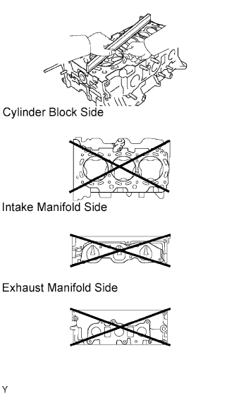
Inspect for flatness.
-
Using a precision straightedge and feeler gauge, measure the surfaces contacting the cylinder block and manifolds for warpage.
Maximum warpage 0.10 mm (0.0039 in.) If the warpage is greater than the maximum, replace the cylinder head.
-
-
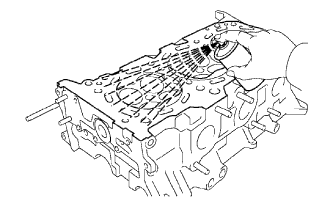
Inspect for cranks.
-
Using a dye penetrant, check the combustion chamber, intake ports, exhaust ports and cylinder block surface for cracks.
If cracked, replace the cylinder head.
-
-
-
INSPECT VALVE
-
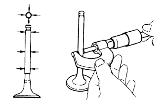
Inspect for valve stem diameter.
-
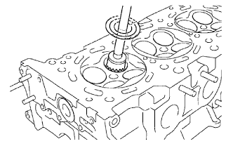
Using a micrometer, measure the diameter of the valve stem.
Valve stem diameter Item Specified Condition Intake 5.470 to 5.485 mm (0.2154 to 0.2159 in.) Exhaust 5.465 to 5.480 mm (0.2152 to 0.2158 in.)
-
-
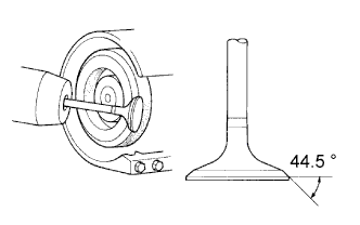
Inspect for valve face angle.
-
Grind the valve enough to remove pits and carbon.
-
Check that the valve is ground to the correct valve face angle.
Valve face angle 44.5°
-
-
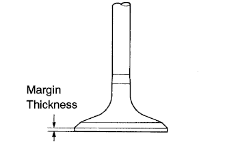
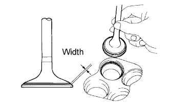
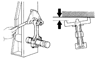
Inspect for valve head margin thickness.
-
Using a vernier calipers, check the valve head margin thickness.
Standard margin thickness 1.0 mm (0.039 in.) Minimum margin thickness 0.5 mm (0.020 in.) If the margin thickness is less than the minimum, replace the valve.
-
-
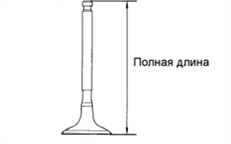
Inspect for overall length.
-
Using a vernier calipers, check the overall length.
Standard overall length Item Specified Condition Intake 106.95 mm (4.2106 in.) Exhaust 105.80 mm (4.1654 in.) Minimum overall length Item Specified Condition Intake 106.40 mm (4.1890 in.) Exhaust 105.30 mm (4.1457 in.) If the overall length is less than the minimum, replace the valve.
-
-
Inspect for valve stem tip.
-
Check the surface of the valve stem tip for wear.
Note
Do not grind off more than the minimum length.
If the valve stem tip is worn, resurface the tip with a grinder or replace the valve.
-
-
-
CLEAN VALVE SEAT
-
Using a 45° carbide cutter, resurface the valve seats.
-
Remove only enough metal to clean the valve seats.
-
-
INSPECT VALVE SEAT
-
Apply a light coat of Prussian blue (or white lead) to the valve face.
-
Lightly press the valve against the valve seat.
Note
Do not rotate the valve.
-
Check the valve face and seat according to the following procedure.
-
If blue appears 360° around the face, the valve is concentric.
If not, replace the valve.
-
If blue appears 360° around the valve seat, the guide and face are concentric.
If not, resurface the valve seat.
-
Check that the seat contact is in the middle of the valve face with these width.
Standard width 1.0 to 1.4 mm (0.039 to 0.055 in.)
-
-
-
INSPECT COMPRESSION SPRING
-
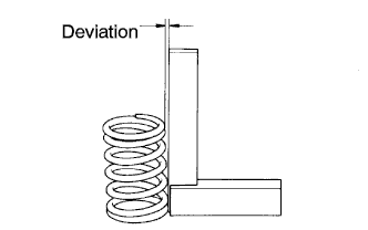
Inspect for squareness.
-
Using a steel square, measure the squareness of the inner compression spring.
Maximum deviation 2.0 mm (0.079 in.) If the deviation is greater than the maximum, replace the inner compression spring.
-
-
Inspect for free length.
-
Using a vernier calipers, measure the free length of the inner compression spring.
Free length 47.80 mm (1.8819 in.) If the free length is not as specified, replace the inner compression spring.
-
-
Inspect for tension.
-
Using a spring tester, measure the tension of the inner compression spring at the specified installed length.
Installed tension 186.2 to 205.8 N (19.0 to 21.0 kgf, 41.9 to 46.3 lbf) at 33.3 mm (1.311 in.) If the installed tension is not specified, replace the inner compression spring.
-
-
-
INSPECT VALVE GUIDE BUSH OIL CLEARANCE
-
Using a caliper gauge, measure the inside diameter of the valve guide bush.
Inside diameter 5.51 to 5.53 mm (0.2169 to 0.2177 in.) -
Subtract the valve stem diameter measurement (see "INSPECT VALVE: Inspect valve stem diameter" procedures above) from the valve guide bush inside diameter measurement.
Standard oil clearance Item Specified Condition Intake 0.025 to 0.060 mm (0.0010 to 0.0024 in.) Exhaust 0.030 to 0.065 mm (0.0012 to 0.0026 in.) Maximum oil clearance Item Specified Condition Intake 0.08 mm (0.0031 in.) Exhaust 0.10 mm (0.0039 in.) If the oil clearance is greater than the maximum, replace the valve and valve guide bush.
-
-
INSPECT VALVE LIFTER
-
Using a micrometer measure the valve lifter diameter.
Valve lifter diameter 30.966 to 30.976 mm (1.2191 to 1.2195 in.)
-
-
INSPECT VALVE LIFTER OIL CLEARANCE
-
Using a caliper gauge, measure the lifter bore diameter of the cylinder head.
Lifter bore diameter 31.009 to 31.025 mm (1.2208 to 1.2215 in.) -
Subtract the valve lifter diameter measurement (see "INSPECT VALVE LIFTER" procedures above) from the lifter bore diameter measurement.
Standard oil clearance 0.033 to 0.059 mm (0.0013 to 0.0023 in.) Maximum oil clearance 0.08 mm (0.0031 in.) If the oil clearance is greater than the maximum, replace the valve lifter.
If necessary, replace the cylinder head.
-
-
INSPECT CAMSHAFT OIL CLEARANCE
-
Clean the camshaft bearing caps, camshaft bearings and camshaft journals.
-
Install the camshaft bearing.
-
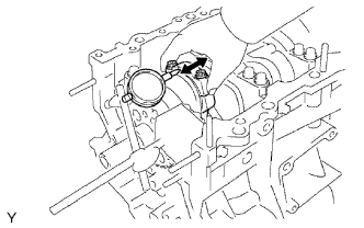
Place the camshaft on the cylinder head.
-
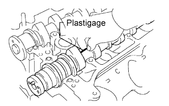
Lay a strip of Plastigage across each of the camshaft journals.
-
Install the camshaft bearing caps.
Note
Do not turn the camshafts.
-
Remove the camshaft bearing caps.
-
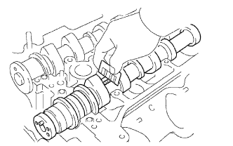
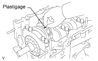
Measure the Plastigage at its widest point.
Standard oil clearance (Cylinder head RH) Item Specified Condition No. 1
(Intake)
0.008 to 0.038 mm (0.0003 to 0.0015 in.) No. 1
(Exhaust)
0.040 to 0.079 mm (0.0016 to 0.0031 in.) Others 0.025 to 0.062 mm (0.0010 to 0.0024 in.) Standard oil clearance (Cylinder head LH) Item Specified Condition No. 1 0.040 to 0.079 mm (0.0016 to 0.0031 in.) Others 0.025 to 0.062 mm (0.0010 to 0.0024 in.) Maximum oil clearance (Cylinder head RH) Item Specified Condition No. 1 0.07 mm (0.0028 in.) Others 0.10 mm (0.0039 in.) Maximum oil clearance (Cylinder head LH) 0.10 mm (0.0039 in.) If the oil clearance is greater than the maximum, replace the camshaft bearings and/or camshaft.
If necessary, replace the camshaft bearing caps and cylinder head as a set.
Reference Item Specified Condition Cylinder head journal bore diameter 40.009 to 40.017 mm (1.5752 to 1.5755 in.) Camshaft bearing center wall thickness (Mark "2") 2.004 to 2.008 mm (0.0789 to 0.0791 in.) Camshaft journal diameter 35.971 to 35.985 mm (1.4165 to 1.4167 in.) -
Remove the Plastigage completely.
-
Remove the camshafts.
-
Remove the camshaft bearing.
-
-
INSPECT CAMSHAFT THRUST CLEARANCE
-
Install the camshafts.
-
Using a dial indicator, measure the thrust clearance while moving the camshaft back and forth.
Standard thrust clearance 0.04 to 0.09 mm (0.016 to 0.035 in.) Maximum thrust clearance 0.11 mm (0.0043 in.) If the thrust clearance is greater than the maximum, replace the camshafts.
If necessary, replace the camshaft bearing caps and cylinder head as a set.
-
-
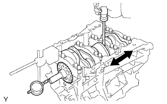
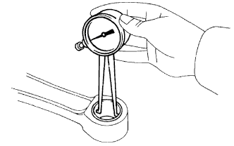
INSPECT CONNECTING ROD THRUST CLEARANCE
-
Using a dial indicator, measure the thrust clearance while moving the connecting rod back and forth.
Standard thrust clearance 0.15 to 0.30 mm (0.0059 to 0.0118 in.) Maximum thrust clearance 0.35 mm (0.0138 in.)
-
-
INSPECT CONNECTING ROD OIL CLEARANCE
-
Check the matchmarks on the connecting rod and cap are aligned to ensure correct reassemble.
-
Using SST, remove the 2 connecting rod cap bolts.
- SST
- 09011-38121
-
Clean the crank pin, bearing and connecting rod.
-
Check the crank pin and bearing for pitting and scratches.
-
Lay a strip of Plastigage across the crank pin.
-
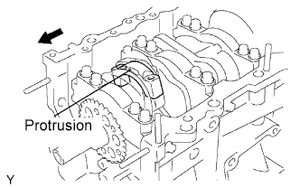
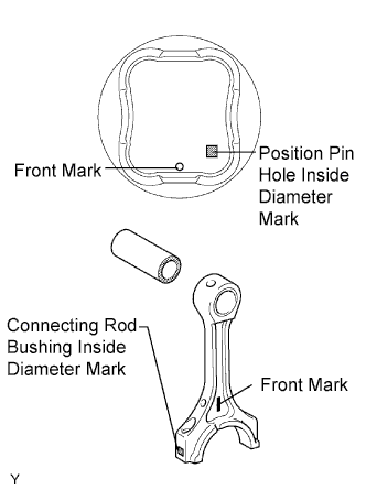
Check that the protrusion of the connecting rod cap is facing in the correct direction.
-
Apply a light coat of engine oil on the threads and under the heads of the connecting rod cap bolts.
-
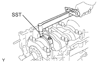
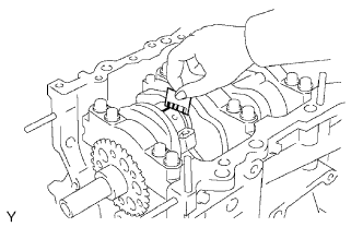
Using SST, tighten the bolts in several passes by the specified torque.
- SST
- 09011-38121
- Torque:
- 25 N*m { 250 kgf*cm, 18 ft.*lbf }
-
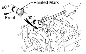
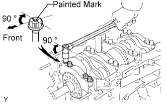
Mark the front side of the each connecting cap bolt with paint.
-
Retighten the cap bolts by 90°shown in the illustration.
Note
Do not turn the crankshaft.
-
Remove the 2 bolts, connecting rod cap and lower bearing.
-
Measure the Plastigage at its widest point.
Standard oil clearance 0.026 to 0.046 mm (0.0010 to 0.0018 in.) Maximum oil clearance 0.066 mm (0.0025 in.) Note
Completely remove the Plastigage.
-
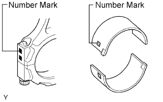
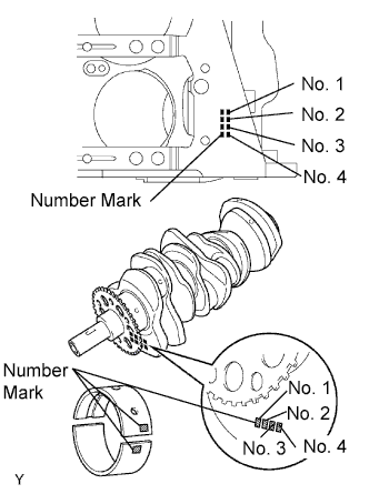
If replace the bearing, replace it with one having the same number as marked on the connecting rod. There are 4 sizes of standard bearings, marked 1, 2, 3 and 4 accordingly.
Standard bearing center wall thickness Mark Specified Condition 1 1.484 to 1.487 mm (0.0584 to 0.0585 in.) 2 1.487 to 1.490 mm (0.0585 to 0.0587 in.) 3 1.490 to 1.493 mm (0.0587 to 0.0588 in.) 4 1.493 to 1.496 mm (0.0588 to 0.0589 in.)
-
-
INSPECT CRANKSHAFT THRUST CLEARANCE
-
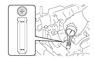
Using a dial indicator, measure the thrust clearance while prying the crankshaft back and forth with a screwdriver.
Standard thrust clearance 0.04 to 0.24 mm (0.0016 to 0.0094 in.) Maximum thrust clearance 0.30 mm (0.0118 in.) If the thrust clearance is greater than the maximum, replace the thrust washers as a set or a crankshaft.
Tech Tips
Thrust washer thickness 1.93 to 1.98 mm (0.0760 to 0.0780 in.)
-
-
INSPECT CYLINDER BLOCK FOR FLATNESS
-
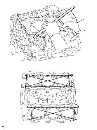
Using a precision straightedge and feeler gauge, measure the surface contacting the cylinder head gasket for warpage.
Maximum warpage 0.05 mm (0.0020 in.) If the warpage is greater than the maximum, replace the cylinder block.
-
-
INSPECT CYLINDER BORE
-
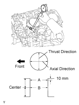
Using a cylinder gauge, measure the cylinder bore diameter at positions A and B in the thrust and axial directions.
Standard diameter 94.000 to 94.012 mm (3.7008 to 3.7013 in.) Maximum diameter 94.132 mm (3.7060 in.) If the average diameter of 4 positions is greater than the maximum, replace the cylinder block.
-
-
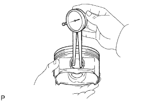
INSPECT PISTON
-
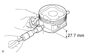
Using a micrometer, measure the piston diameter at right angles to the piston pin center line, 27.7 mm (1.091 in.) from the piston head.
Piston diameter 93.910 to 93.920 mm (3.6972 to 3.6976 in.)
-
-
INSPECT PISTON OIL CLEARANCE
-
Subtract the piston diameter measurement from the cylinder bore diameter measurement.
Standard oil clearance 0.080 to 0.102 mm (0.0031 to 0.0040 in.) Maximum oil clearance 0.13 mm (0.0051 in.) If the oil clearance is greater than the maximum, replace all the 6 pistons. If necessary, replace the cylinder block.
-
-
INSPECT CONNECTING ROD
-
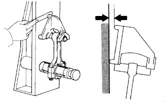
Using a rod aligner and feeler gauge, check the connecting rod alignment.
-
Check for out-of alignment.
Maximum out-of alignment 0.05 mm (0.0020 in.) per 100 mm (3.94 in.) If out-of alignment is greater than the maximum, replace the connecting rod assembly.
-
Check of twist.
Maximum twist 0.15 mm (0.0059 in.) per 100 mm (3.94 in.) If the twist is greater than the maximum, replace the connecting rod assembly.
-
-
-
INSPECT PISTON PIN OIL CLEARANCE
-
Using a caliper gauge, measure the inside diameter of the piston pin hole.
Piston pin hole inside diameter 22.001 to 22.010 mm (0.8662 to 0.8665 in.) Piston pin hole inside diameter Mark Specified Condition A 22.001 to 22.004 mm (0.8662 to 0.8663 in.) B 22.005 to 22.007 mm (0.8663 to 0.8664 in.) C 22.008 to 22.010 mm (0.8665 to 0.8665 in.) -
Using a micrometer, measure the piston pin diameter.
Piston pin diameter 21.997 to 22.006 mm (0.8660 to 0.8664 in.) Piston pin diameter Mark Specified Condition A 21.997 to 22.000 mm (0.8660 to 0.8661 in.) B 22.001 to 22.003 mm (0.8661 to 0.8663 in.) C 22.004 to 22.006 mm (0.8663 to 0.8664 in.) -
Using a caliper gauge, measure the inside diameter of the connecting rod bushing.
Bushing inside diameter 22.005 to 22.014 mm (0.8663 to 0.8667 in.) Bushing inside diameter Mark Specified Condition A 22.005 to 22.008 mm (0.8663 to 0.8665 in.) B 22.009 to 22.011 mm (0.8665 to 0.8666 in.) C 22.012 to 22.014 mm (0.8666 to 0.8667 in.) -
Subtract the piston pin diameter measurement from the piton pin hole diameter measurement.
Standard oil clearance 0.001 to 0.007 mm (0.00004 to 0.00028 in.) Maximum oil clearance 0.040 mm (0.0016 in.) If the oil clearance is greater than the maximum, replace the bushing. If necessary, replace the piston and piston pin as a set.
-
Subtract the piston pin diameter measurement from the bushing inside diameter measurement.
Standard oil clearance 0.005 to 0.011 mm (0.0002 to 0.0004 in.) Maximum oil clearance 0.050 mm (0.0020 in.) If the oil clearance is greater than the maximum, replace the bushing. If necessary, replace the connecting rod and piston pin as a set.
-
-
INSPECT RING GROOVE CLEARANCE
-
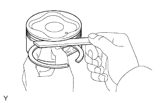
Using a feeler gauge, measure the clearance between a new piston ring and the wall of the ring groove.
Ring groove clearance Ring Groove Clearance No.1 0.02 to 0.07 mm (0.0008 to 0.0028 in.) No.2 0.02 to 0.06 mm (0.0008 to 0.0024 in.) Oil 0.07 to 0.15 mm (0.0028 to 0.0060 in.)
-
-
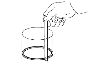
INSPECT PISTON RING END GAP
-
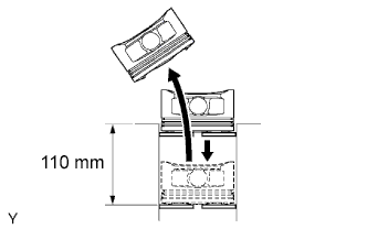
Using a piston, push the piston ring a little beyond the bottom of the ring travel, 110 mm (4.33 in.) from the top of the cylinder block.
-
Using a feeler gauge, measure the end gap.
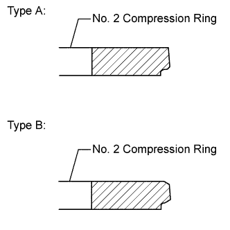
Standard End Gap (for Type A) Item Specified Condition No. 1 Compression Ring 0.30 to 0.40 mm (0.0118 to 0.0157 in.) No. 2 Compression Ring 0.40 to 0.50 mm (0.0157 to 0.0197 in.) Oil Ring (Side Rail) 0.10 to 0.40 mm (0.00394 to 0.0157 in.) Standard End Gap (for Type B) Item Specified Condition No. 1 Compression Ring 0.22 to 0.32 mm (0.00866 to 0.0126 in.) No. 2 Compression Ring 0.35 to 0.45 mm (0.0138 to 0.0177 in.) Oil Ring (Side Rail) 0.10 to 0.40 mm (0.00394 to 0.0157 in.) Maximum End Gap Item Specified Condition No. 1 Compression Ring 1.0 mm (0.0394 in.) No. 2 Compression Ring 1.1 mm (0.0433 in.) Oil Ring (Side Rail) 1.0 mm (0.0394 in.) Tech Tips
Type A and type B can be distinguished by the color of the paint marks or the cross-section shape of the No. 2 compression ring.
Item Paint Mark Type A No. 1 Compression Ring - No. 2 Compression Ring Orange Type B No. 1 Compression Ring Blue No. 2 Compression Ring Blue If the end gap is more than the maximum, replace the piston ring. If the end gap is more than the maximum, even with a new piston ring, replace the cylinder block.
-
-
INSPECT CONNECTING ROD BOLT
-
Using a vernier caliper, measure the tension portion diameter of the bolt.
Standard diameter 7.2 to 7.3 mm (0.283 to 0.287 in.) Minimum diameter 7.0 mm (0.276 in.) If the diameter is less than the minimum, replace the bolt.
-
-
INSPECT CRANKSHAFT BEARING CAP SET BOLT
-
Using a vernier caliper, measure the tension portion diameter of the bolt.
Standard diameter 10.0 to 10.2 mm (0.393 to 0.402 in.) If the diameter is less than the minimum, replace the bolt.
-
-
INSPECT CRANKSHAFT
-
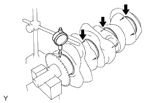
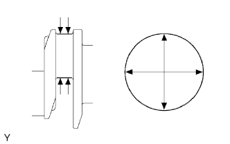
Using a dial indicator and V-blocks, measure the circle runout, as shown in the illustration.
Maximum circle runout 0.06 mm (0.0024 in.) -
Using a micrometer, measure the diameter of each main journal.
Diameter 71.988 to 72.000 mm (2.8342 to 2.8346 in.) -
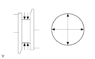
Check each main journal for taper and out-of-round as shown.
Maximum taper and out-of-round 0.02 mm (0.0008 in.) -
Using a micrometer, measure the diameter of each crank pin.
Diameter 55.992 to 56.000 mm (2.2044 to 2.2047 in.) -
Check each crank pin for taper and out-of-round as shown.
Maximum taper and out-of-round 0.02 mm (0.0008 in.)
-
-
INSPECT CRANKSHAFT OIL CLEARANCE
Tech Tips
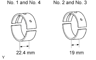
Main bearings come in widths of 19.0 mm (0.748 in.) and 22.4 mm (0.882 in.). Install the 22.4mm (0.882 in.) bearings in the No. 1 and No. 4 cylinder block journal positions with the main bearing cap. Install the 19.0 mm (0.748 in.) bearings in the No. 2 and No. 3 positions.
-
Clean each main journal and bearing.
-
Align the bearing claw with the claw groove of the cylinder block, and push in the 4 upper bearings.
Note
Do not apply engine oil to the bearing and its contact surface.
-
Align the bearing claw with the claw groove of the main bearing cap, and push in the 4 lower bearings.
Note
Do not apply engine oil to the bearing and its contact surface.
Tech Tips
A number is marked on each main bearing cap to indicate the installation position.
-
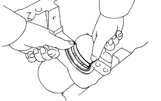
Place the crankshaft on the cylinder block.
-
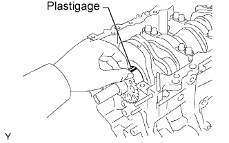
Lay a strip of Plastigage across each journal.
-
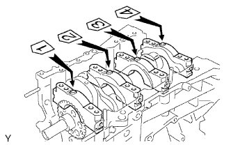
Examine the front marks and numbers and install the bearing caps on the cylinder block.
-
Apply a light coat of engine oil on the threads and under the head of bearing cap bolts.
-
Temporarily install the 8 main bearing cap bolts to the inside positions.
-
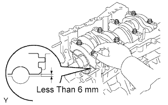
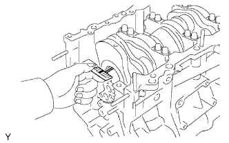
Insert the main bearing cap with hand until the clearance between the main bearing cap and the cylinder block will become less than 6 mm (0.23 in.) by making the 2 internal bearing cap bolts as a guide.
-
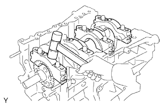
Using a plastic-faced hammer, lightly tap the bearing cap to ensure a proper fit.
-
Apply a light coat of engine oil on the threads and under the head of main bearing cap bolts.
-
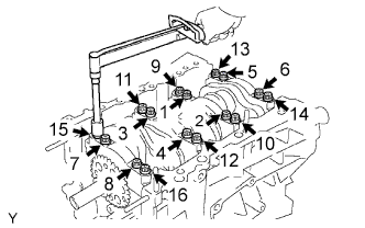
Install and uniformly tighten the 16 main bearing cap bolts in several passes, in the sequence shown.
- Torque:
- 61 N*m { 622 kgf*cm, 45 ft.*lbf }
-
Mark the front side of the bearing cap bolts with paint.
-
Retighten the bearing cap bolts by 90° in the sequence shown.
-
Check that the painted mark is now at a 90° angle to the front.
Note
Do not turn the crankshaft.
-
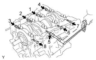
Install and uniformly tighten the 8 main bearing cap bolts in several passes, in the sequence shown.
- Torque:
- 35 N*m { 357 kgf*cm, 26 ft.*lbf }
-
Remove the main bearing caps.
-
Measure the Plastigage at its widest point.
Standard oil clearance 0.018 to 0.030 mm (0.0007 to 0.0012 in.) Maximum clearance 0.046 mm (0.0018 in.) If the oil clearance is greater than the maximum, replace the bearings. If necessary, replace the crankshaft.
Note
Completely remove the Plastigage.
-
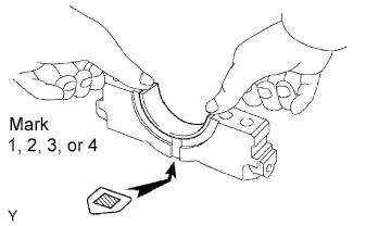
Using a bearing, replace it with one having the same number. If the number of the bearing cannot be determined, select the correct bearing by adding together the numbers imprinted on the cylinder block and crankshaft, then refer to the table below for the appropriate bearing number. There are 5 size of standard bearings, marked 1, 2, 3, 4 and 5 accordingly.
Journal bearing Cylinder block (A)
+
Crankshaft
0 to 5 6 to 11 12 to 17 18 to 23 24 to 28 Use Bearing 1 2 3 4 5 Tech Tips
EXAMPLE
Cylinder block "11" (A) + Crankshaft "06" (B)
= Total number 17 (Use bearing "3")
Cylinder block main journal bore diameter (A) Mark Specified Condition 00 77.000 mm (3.0315 in.) 01 77.001 mm (3.0315 in.) 02 77.002 mm (3.0316 in.) 03 77.003 mm (3.0316 in.) 04 77.004 mm (3.0317 in.) 05 77.005 mm (3.0317 in.) 06 77.006 mm (3.0317 in.) 07 77.007 mm (3.0318 in.) 08 77.008 mm (3.0318 in.) 09 77.009 mm (3.0319 in.) 10 77.010 mm (3.0319 in.) 11 77.011 mm (3.0319 in.) 12 77.012 mm (3.0320 in.) 13 77.013 mm (3.0320 in.) 14 77.014 mm (3.0320 in.) 15 77.015 mm (3.0321 in.) 16 77.016 mm (3.0321 in.) Crankshaft main journal diameter (B) Mark Specified Condition 00 71.999 to 72.000 mm (2.8346 to 2.8346 in.) 01 71.998 to 71.999 mm (2.8346 to 2.8346 in.) 02 71.997 to 71.998 mm (2.8345 to 2.8346 in.) 03 71.996 to 71.997 mm (2.8345 to 2.8346 in.) 04 71.995 to 71.996 mm (2.8344 to 2.8345 in.) 05 71.994 to 71.995 mm (2.8344 to 2.8344 in.) 06 71.993 to 71.994 mm (2.8343 to 2.8344 in.) 07 71.992 to 71.993 mm (2.8343 to 2.8343 in.) 08 71.991 to 71.992 mm (2.8343 to 2.8343 in.) 09 71.990 to 71.991 mm (2.8343 to 2.8343 in.) 10 71.989 to 71.990 mm (2.8342 to 2.8343 in.) 11 71.988 to 71.989 mm (2.8342 to 2.8342 in.) Standard bearing center wall thickness Mark Specified Condition 01 2.488 to 2.491 mm (0.0980 to 0.0981 in.) 02 2.491 to 2.494 mm (0.0981 to 0.0982 in.) 03 2.494 to 2.497 mm (0.0982 to 0.0983 in.) 04 2.497 to 2.500 mm (0.0982 to 0.0984 in.) 05 2.500 to 2.503 mm (0.0984 to 0.0985 in.)
-
-
INSPECT NO. 1 OIL NOZZLE SUB-ASSEMBLY
-
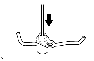
Push the check valve with a pin to check if it is stuck. If stuck, replace the oil nozzle.
-
Push the check valve with a pin to check if it moves smoothly.
If it does not move smoothly, clean or replace the oil nozzle.
-
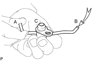
While covering A, blow air into B. Check that air does not leak through C. Perform the check again while covering B and blowing air into A.
If air leaks, clean or replace the oil nozzle.
-
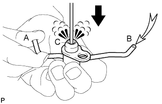
Push the check valve while covering A, and blow air into B. Check that air passes through C. Perform the check again while covering B, pushing the check valve and blowing air into A.
If air does not pass through C, clean or replace the oil nozzle.
-