OIL PUMP INSTALLATION
PROCEDURE
-
INSTALL TIMING CHAIN OR BELT COVER SUB-ASSEMBLY
-
Apply a light coat of engine oil to the 4 O-rings.
-
Remove any old packing material remaining on the sealing surfaces before applying seal packing.
-
If there are gaps at positions shown in the illustration, fill up with seal packing by using a sealer gun.
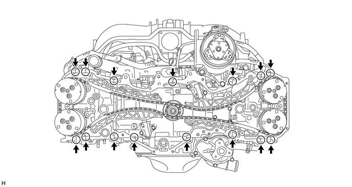
Seal packing Three Bond 1217G, 1217H or equivalent -
Using a sealer gun, apply seal packing in a continuous line to the timing chain cover as shown in the following illustration.
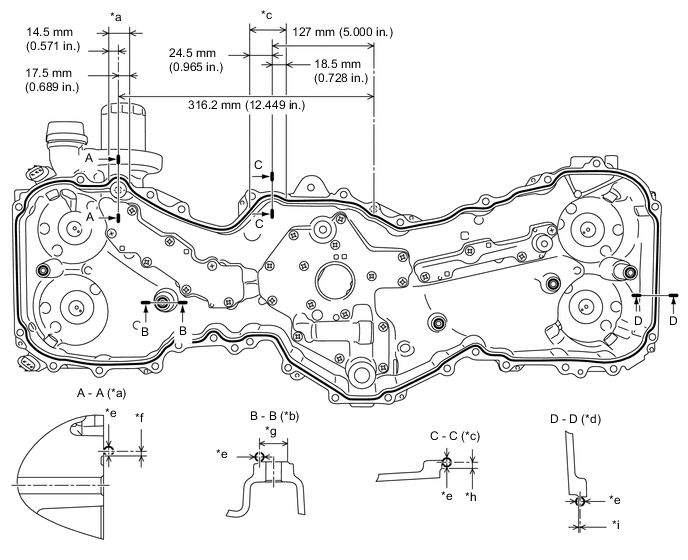
Text in Illustration *a Range A *b Boss (5 locations) *c Range B *d Other than ranges A and B *e φ3.5 to 4.5 mm (0.138 to 0.177 in.) *f 2 mm (0.079 in.) *g φ12 mm (0.472 in.) *h 2.5 mm (0.098 in.) *i 0.5 mm (0.020 in.) - - Seal packing Three Bond 1217G, 1217H or equivalent Note
-
If the contact surfaces are wet, wipe them with an oil-free cloth before applying seal packing.
-
Install the chain cover within 3 minutes and tighten the bolts within 10 minutes after applying seal packing.
-
Do not add engine oil for at least 2 hours after installing.
-
Do not start the engine for at least 2 hours after installing.
-
-
Temporarily tighten the timing chain cover with the 32 bolts.
-
Fully tighten the 32 bolts shown in the illustration.
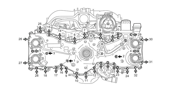
Text in Illustration 
Bolt A 
Bolt B 
Bolt C 
Bolt D - Torque:
- for bolt A and B
- 10 N*m { 102 kgf*cm, 7 ft.*lbf }
- for bolt C and D
- 25 N*m { 255 kgf*cm, 18 ft.*lbf }
Bolt Length Item Length Item Length Bolt A 20 mm (0.787 in.) Bolt B 50 mm (1.969 in.) Bolt C 25 mm (0.984 in.) Bolt D 60 mm (2.362 in.)
-
-
INSTALL TIMING CHAIN OR BELT COVER OIL SEAL
-
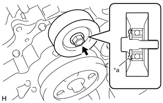
INSTALL NO. 1 IDLER PULLEY SUB-ASSEMBLY
-
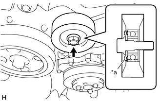
Text in Illustration *a Protrusion Install the washer plate to the No. 1 idler pulley sub-assembly as shown in the illustration.
-
Install the washer plate and No. 1 idler pulley sub-assembly with the bolt.
- Torque:
- 36 N*m { 367 kgf*cm, 27 ft.*lbf }
-
Text in Illustration *a Protrusion Install the washer plate to the No. 1 idler pulley sub-assembly as shown in the illustration.
-
Install the washer plate and No. 1 idler pulley sub-assembly with the bolt.
- Torque:
- 36 N*m { 367 kgf*cm, 27 ft.*lbf }
-
-
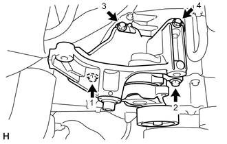
INSTALL V-RIBBED BELT TENSIONER ASSEMBLY
-
Temporarily install the V-ribbed belt tensioner with the 5 bolts.
-
Tighten the 4 bolts in the order shown in the illustration.
- Torque:
- 36 N*m { 367 kgf*cm, 27 ft.*lbf }
-
-
INSTALL NO. 2 IDLER PULLEY SUB-ASSEMBLY
-
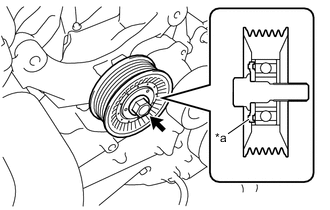
Text in Illustration *a Protrusion Install the washer plate to the No. 2 idler pulley sub-assembly as shown in the illustration.
-
Install the washer plate and No. 2 idler pulley sub-assembly with the bolt.
- Torque:
- 36 N*m { 367 kgf*cm, 27 ft.*lbf }
-
-
INSTALL OIL LEVEL DIPSTICK GUIDE
-
Install a new O-ring to the oil level dipstick guide.
-
Apply a light coat of engine oil to the O-ring.
-
Install the oil level dipstick guide with the bolt.
- Torque:
- 6.4 N*m { 65 kgf*cm, 57 in.*lbf }
-
Install the oil level dipstick sub-assembly.
-
-
CONNECT ENGINE WIRE
-
Connect the camshaft position sensor connector and camshaft timing oil control valve connector.
-
Engage the wire harness clamp.
-
Connect the engine oil pressure switch connector and engine oil temperature sensor connector.
-
Connect the camshaft position sensor connector and camshaft timing oil control valve connector.
-
Connect the 2 camshaft position sensor connectors and camshaft timing oil control valve connector.
-
Connect the camshaft position sensor connector.
-
Install the wire harness bracket with the bolt.
- Torque:
- 6.4 N*m { 65 kgf*cm, 57 in.*lbf }
-
Engage the wire harness clamp.
-
Install the 2 wire harness brackets with the 2 bolts.
- Torque:
- 6.4 N*m { 65 kgf*cm, 57 in.*lbf }
-
-
INSTALL INJECTOR COVER (for Bank 1)
-
INSTALL CRANKSHAFT PULLEY
-
INSTALL WATER PUMP PULLEY
-
CONNECT RADIATOR OUTLET HOSE
-
INSTALL EXHAUST MANIFOLD
-
INSTALL WATER FILLER SUB-ASSEMBLY
-
INSTALL RADIATOR RESERVE TANK ASSEMBLY
-
INSTALL INJECTOR DRIVER
-
INSTALL GENERATOR ASSEMBLY
-
ADD ENGINE COOLANT
-
ADD ENGINE OIL
-
INSPECT FOR ENGINE OIL LEAK
-
CHECK ENGINE OIL LEVEL