METER / GAUGE SYSTEM Speedometer Malfunction
| DTC Code | DTC Name |
|---|---|
| Speedometer Malfunction |
DESCRIPTION
The combination meter receives vehicle speed signals from the skid control ECU via the CAN line. The wheel speed sensors output voltages that vary according to the vehicle speed. The skid control ECU supplies power to the wheel speed sensors. The skid control ECU calculates the vehicle speed based on the pulses of the voltage.
WIRING DIAGRAM
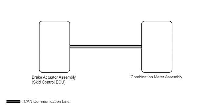
PROCEDURE
CHECK CAN COMMUNICATION SYSTEM
Check for DTCs (Click here).
Table 1. Result Result
Proceed to
CAN communication system DTC is not output
A
CAN communication system DTC is output
B
CHECK BRAKE CONTROL SYSTEM (VEHICLE SPEED)
Check for DTCs (Click here).
Table 2. Result Result
Proceed to
No DTCs are output
A
DTCs are output
B
PERFORM ACTIVE TEST USING INTELLIGENT TESTER (SPEEDOMETER)
Use the Active Test to check the operation of the speedometer (Click here).
Table 3. Combination Meter Tester Display
Test Part
Control Range
Diagnostic Note
Speed Meter Operation
Speedometer
0, 40, 80, 120, 160, 200 or 240
Perform the test with the vehicle stopped and the engine idling.
Tip:Make sure that the vehicle is stopped and the engine is idling. The doors will be locked automatically when performing the speedometer Active Test. This is a normal function.
The displayed value has the same units (km/h, mph) as the main scale of the vehicle speedometer.
The needle position should be within the acceptable range.
OK
Needle indication is normal.
READ VALUE USING INTELLIGENT TESTER (VEHICLE SPEED)
Use the Data List to check if the speedometer is operating properly (Click here).
Table 4. Combination Meter Tester Display
Measurement Item/Range
Normal Condition
Diagnostic Note
Vehicle Speed Meter
Vehicle speed/Min.: 0 (0), Max.: 255 (158)
Almost same as actual speed (when driving)
Unit: km/h (mph)
OK
Vehicle speed displayed on the intelligent tester is almost the same as the actual vehicle speed measured using a speedometer tester (calibrated chassis dynamometer).
READ VALUE USING INTELLIGENT TESTER (WHEEL SPEED SENSOR)
Use the Data List to check the wheel speed (Click here).
Table 5. ABS/VSC/TRAC Tester Display
Measurement Item/Range
Normal Condition
Diagnostic Note
FR Wheel Speed
Wheel speed sensor FR reading/Min.: 0 (0), Max.: 326 (202)
Actual wheel speed
A similar speed is indicated on the speedometer.
FL Wheel Speed
Wheel speed sensor FL reading/Min.: 0 (0), Max.: 326 (202)
Actual wheel speed
A similar speed is indicated on the speedometer.
RR Wheel Speed
Wheel speed sensor RR reading/Min.: 0 (0), Max.: 326 (202)
Actual wheel speed
A similar speed is indicated on the speedometer.
RL Wheel Speed
Wheel speed sensor RL reading/Min.: 0 (0), Max.: 326 (202)
Actual wheel speed
A similar speed is indicated on the speedometer.
OK
Wheel speed displayed on the intelligent tester is almost the same as the actual wheel speed measured using a speedometer tester (calibrated chassis dynamometer).
REPLACE COMBINATION METER ASSEMBLY
Temporarily replace the combination meter with a new one or normally functioning one (Click here).
CHECK COMBINATION METER ASSEMBLY
Check that the operation of the combination meter returns to normal (Click here).
OK
Operation of combination meter returns to normal.
END (COMBINATION METER ASSEMBLY IS DEFECTIVE)