REAR SUSPENSION MEMBER INSTALLATION

PROCEDURE
-
INSTALL REAR SUSPENSION MEMBER FRONT BODY MOUNTING CUSHION (for LH Side)
-
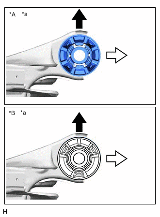
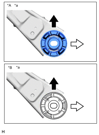
*A Type A *B Type B *a View from Underneath 
Front of the Vehicle 
Outside of the Vehicle Confirm the installation direction and temporarily install a new rear suspension member front body mounting cushion.
Note
-
Position the rear suspension member front body mounting cushion in the correct direction.
-
Do not apply lubricant to the outer sleeve of the rear suspension member front body mounting cushion.
-
-
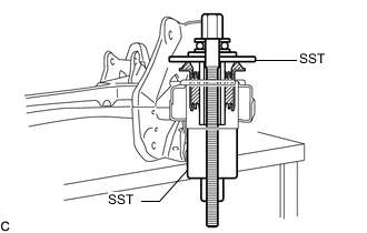
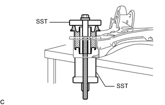
Install SST as shown in the illustration.
- SST
- 09570-24011
- 09830-10010 ( 09830-01010, 09830-01020, 09830-01040, 09830-01050 )
Note
Apply molybdenum grease to the threads and tip of the SST center bolt before use.
-
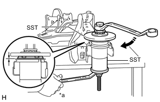
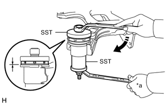
*a Hold 
Turn Using SST, install the rear suspension member front body mounting cushion until there is no clearance between the rear suspension member sub-assembly and rear suspension member front body mounting cushion.
- SST
- 09570-24011
- 09830-10010 ( 09830-01010, 09830-01020, 09830-01040, 09830-01050 )
Note
If the rear suspension member sub-assembly is scratched, apply paint to the scratched areas of the rear suspension member sub-assembly.
-
Remove SST from the rear suspension member sub-assembly.
-
-
INSTALL REAR SUSPENSION MEMBER FRONT BODY MOUNTING CUSHION (for RH Side)
-
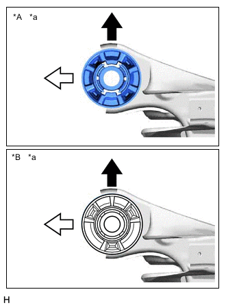
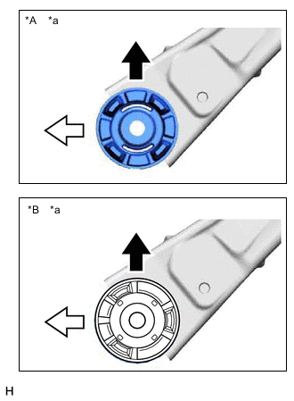
*A Type A *B Type B *a View from Underneath Front of the Vehicle Outside of the Vehicle Confirm the installation direction and temporarily install a new rear suspension member front body mounting cushion.
Note
-
Position the rear suspension member front body mounting cushion in the correct direction.
-
Do not apply lubricant to the outer sleeve of the rear suspension member front body mounting cushion.
-
-
Install SST using the same procedure as for the rear suspension member front body mounting cushion (for LH Side).
- SST
- 09570-24011
- 09830-10010 ( 09830-01010, 09830-01020, 09830-01040, 09830-01050 )
Note
Apply molybdenum grease to the threads and tip of the SST center bolt before use.
-
Using SST, install the rear suspension member front body mounting cushion until there is no clearance between the rear suspension member sub-assembly and rear suspension member front body mounting cushion.
- SST
- 09570-24011
- 09830-10010 ( 09830-01010, 09830-01020, 09830-01040, 09830-01050 )
Note
If the rear suspension member sub-assembly is scratched, apply paint to the scratched areas of the rear suspension member sub-assembly.
Tech Tips
Perform the same procedure as for the rear suspension member front body mounting cushion (for LH Side).
-
Remove SST from the rear suspension member sub-assembly.
-
-
INSTALL REAR SUSPENSION MEMBER REAR BODY MOUNT CUSHION LH
-
*A Type A *B Type B *a View from Underneath Front of the Vehicle Outside of the Vehicle Confirm the installation direction and temporarily install a new rear suspension member rear body mount cushion LH.
Note
-
Position the rear suspension member rear body mount cushion LH in the correct direction.
-
Do not apply lubricant to the outer sleeve of the rear suspension member rear body mount cushion LH.
-
-
Install SST as shown in the illustration.
- SST
- 09710-28031 ( 09711-02030, 09711-02040, 94622-51200 )
- 09950-60021 ( 09951-00720, 09951-00890 )
Note
Apply molybdenum grease to the threads and tip of the SST center bolt before use.
-
*a Hold Turn Using SST, install the rear suspension member rear body mount cushion LH until there is no clearance between the rear suspension member sub-assembly and rear suspension member rear body mount cushion LH.
- SST
- 09710-28031 ( 09711-02030, 09711-02040, 94622-51200 )
- 09950-60021 ( 09951-00720, 09951-00890 )
Note
If the rear suspension member sub-assembly is scratched, apply paint to the scratched areas of the rear suspension member sub-assembly.
-
Remove SST from the rear suspension member sub-assembly.
-
-
INSTALL REAR SUSPENSION MEMBER REAR BODY MOUNT CUSHION RH
-
*A Type A *B Type B *a View from Underneath Front of the Vehicle Outside of the Vehicle Confirm the installation direction and temporarily install a new rear suspension member rear body mount cushion RH.
Note
-
Position the rear suspension member rear body mount cushion RH in the correct direction.
-
Do not apply lubricant to the outer sleeve of the rear suspension member rear body mount cushion RH.
-
-
Install SST using the same procedure as for the rear suspension member rear body mount cushion LH.
- SST
- 09710-28031 ( 09711-02030, 09711-02040, 94622-51200 )
- 09950-60021 ( 09951-00720, 09951-00890 )
Note
Apply molybdenum grease to the threads and tip of the SST center bolt before use.
-
Using SST, install the rear suspension member rear body mount cushion RH until there is no clearance between the rear suspension member sub-assembly and rear suspension member rear body mount cushion RH.
- SST
- 09710-28031 ( 09711-02030, 09711-02040, 94622-51200 )
- 09950-60021 ( 09951-00720, 09951-00890 )
Note
If the rear suspension member sub-assembly is scratched, apply paint to the scratched areas of the rear suspension member sub-assembly.
Tech Tips
Perform the same procedure as for the rear suspension member rear body mount cushion LH.
-
Remove SST from the rear suspension member sub-assembly.
-
-
INSTALL REAR UPPER CONTROL ARM ASSEMBLY LH
-
INSTALL REAR UPPER CONTROL ARM ASSEMBLY RH
Tech Tips
Perform the same procedure as for the LH side.
-
INSTALL REAR SUSPENSION MEMBER SUB-ASSEMBLY
-
Install the 4 rear suspension member cushions to the rear suspension member sub-assembly.
Tech Tips
When reusing the rear suspension member cushion, make sure to check its identification mark and install it to the correct position.
-
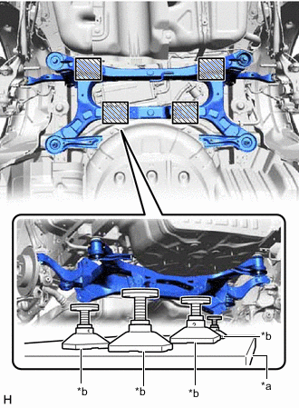
*a Engine Lifter *b Attachment 
Attachment Placement Location Using an engine lifter and 4 attachments or equivalent tools, support the rear suspension member sub-assembly as shown in the illustration.
CAUTION:
-
The rear suspension member sub-assembly is a very heavy component. Make sure that it is supported securely.
-
If the rear suspension member sub-assembly is not securely supported, it may drop, resulting in serious injury.
Note
-
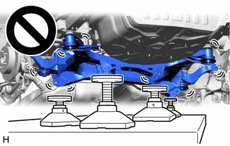
Use attachments or equivalent tools to keep the rear suspension member sub-assembly level.
-
Keep supporting the rear suspension member sub-assembly until the installation has been completed.
-
-
Raise the rear suspension member sub-assembly until there is no clearance between the rear suspension member sub-assembly and vehicle.
-
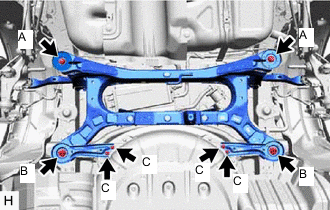
Install the rear suspension member sub-assembly with the 2 rear suspension member lower stoppers, rear suspension member lower brace LH and rear suspension member lower brace RH, 2 bolts and 6 nuts.
- Torque:
- Bolt A
- 158 N*m { 1611 kgf*cm, 117 ft.*lbf }
- Nut B
- 158 N*m { 1611 kgf*cm, 117 ft.*lbf }
- Nut C
- 18 N*m { 184 kgf*cm, 13 ft.*lbf }
-
-
TEMPORARILY INSTALL REAR UPPER CONTROL ARM ASSEMBLY LH
-
Temporarily install the rear upper control arm assembly LH to the rear axle carrier sub-assembly LH with the bolt and nut.
Note
-
Insert the bolt with the threaded end facing the rear of the vehicle.
-
Because the nut has its own stopper, do not turn the nut. Tighten the bolt with the nut secured.
-
-
-
TEMPORARILY INSTALL REAR UPPER CONTROL ARM ASSEMBLY RH
Tech Tips
Perform the same procedure as for the LH side.
-
TEMPORARILY INSTALL REAR NO. 1 SUSPENSION ARM ASSEMBLY LH
-
TEMPORARILY INSTALL REAR NO. 1 SUSPENSION ARM ASSEMBLY RH
Tech Tips
Perform the same procedure as for the LH side.
-
TEMPORARILY INSTALL REAR NO. 2 SUSPENSION ARM ASSEMBLY LH
-
TEMPORARILY INSTALL REAR NO. 2 SUSPENSION ARM ASSEMBLY RH
Tech Tips
Perform the same procedure as for the LH side.
-
INSTALL REAR LOWER COIL SPRING INSULATOR LH
-
INSTALL REAR LOWER COIL SPRING INSULATOR RH
Tech Tips
Perform the same procedure as for the LH side.
-
INSTALL REAR COIL SPRING LH
-
INSTALL REAR COIL SPRING RH
Tech Tips
Perform the same procedure as for the LH side.
-
INSTALL REAR STABILIZER BAR
-
INSTALL REAR HEIGHT CONTROL SENSOR SUB-ASSEMBLY LH (w/ Height Control Sensor)
-
CONNECT REAR FLEXIBLE HOSE LH
-
Connect the rear flexible hose LH to the rear flexible hose bracket with the bolt.
- Torque:
- 29 N*m { 296 kgf*cm, 21 ft.*lbf }
-
-
CONNECT REAR FLEXIBLE HOSE RH
Tech Tips
Perform the same procedure as for the LH side.
-
STABILIZE SUSPENSION
-
INSTALL REAR STABILIZER LINK ASSEMBLY LH
-
INSTALL REAR STABILIZER LINK ASSEMBLY RH
Tech Tips
Perform the same procedure as for the LH side.
-
INSTALL REAR NO. 1 SUSPENSION ARM ASSEMBLY LH
-
INSTALL REAR NO. 1 SUSPENSION ARM ASSEMBLY RH
Tech Tips
Perform the same procedure as for the LH side.
-
INSTALL REAR NO. 2 SUSPENSION ARM ASSEMBLY LH
-
Install the rear No. 2 suspension arm assembly LH (rear axle carrier sub-assembly side) with the bolt.
-
-
INSTALL REAR NO. 2 SUSPENSION ARM ASSEMBLY RH
Tech Tips
Perform the same procedure as for the LH side.
-
INSTALL REAR UPPER CONTROL ARM ASSEMBLY LH
-
Install the rear upper control arm assembly LH to the rear axle carrier sub-assembly LH with the bolt.
- Torque:
- 73 N*m { 744 kgf*cm, 54 ft.*lbf }
Note
Because the nut has its own stopper, do not turn the nut. Tighten the bolt with the nut secured.
-
-
INSTALL REAR UPPER CONTROL ARM ASSEMBLY RH
Tech Tips
Perform the same procedure as for the LH side.
-
INSTALL NO. 1 FLOOR UNDER COVER (w/ Cover)
-
INSTALL NO. 2 FLOOR UNDER COVER (w/ Cover)
-
INSTALL CENTER EXHAUST PIPE ASSEMBLY
for 2AR-FE: Click here
for A25A-FKS: Click here
for 2GR-FKS: Click here
-
INSTALL REAR WHEEL
-
INSTALL REAR NO. 2 SUSPENSION ARM ASSEMBLY LH
-
Install the rear No. 2 suspension arm assembly LH (rear suspension member sub-assembly side) with the nut.
-
-
INSTALL REAR NO. 2 SUSPENSION ARM ASSEMBLY RH
Tech Tips
Perform the same procedure as for the LH side.
-
INSPECT FOR EXHAUST GAS LEAK
for 2AR-FE: Click here
for A25A-FKS: Click here
for 2GR-FKS: Click here
-
INSPECT AND ADJUST REAR WHEEL ALIGNMENT
-
PERFORM INITIALIZATION
Parking assist monitor system Click here for Initialization
Click here for Calibration
Lighting System (EXT) (w/ Automatic Headlight Beam Level Control System)