AUTOMATIC TRANSAXLE UNIT REASSEMBLY
PROCEDURE
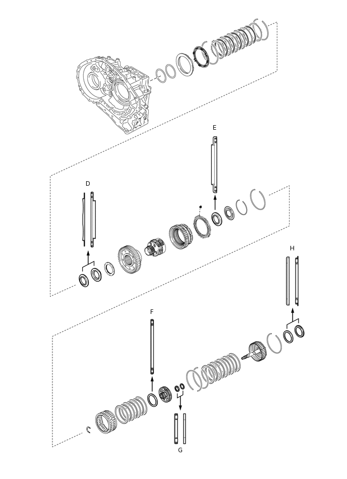
BEARING POSITION
Check bearing position and installation direction.
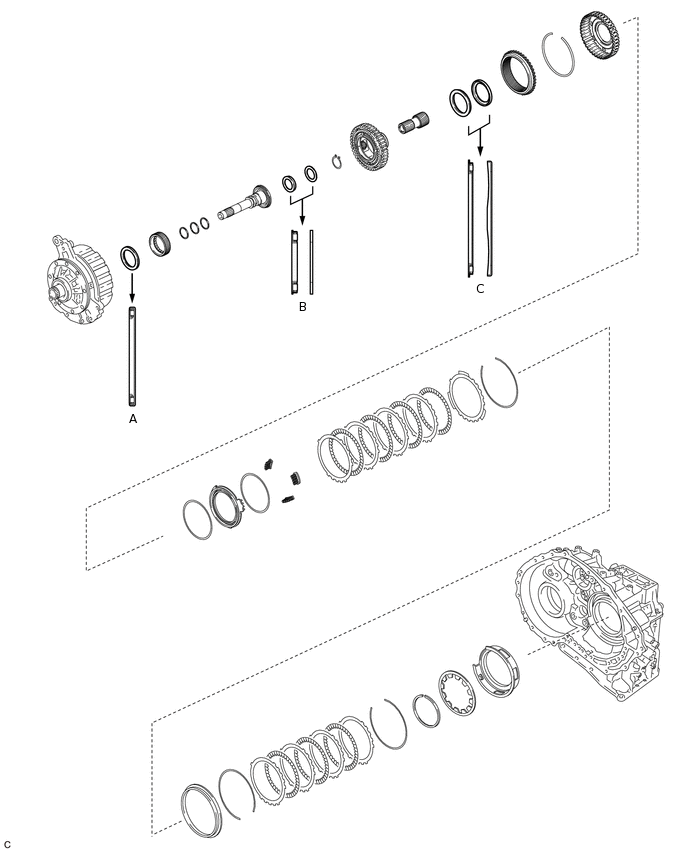
Mark
Front Race Diameter
Inside / Outside
Thrust Bearing Diameter
Inside / Outside
Rear Race Diameter
Inside / Outside mm
A
-
57.7 mm (2.27 in.) / 75.2 mm (2.96 in.)
-
B
-
29.1 mm (1.15 in.) / 48.6 mm (1.91 in.)
30.7 mm (1.21 in.) / 48.3 mm (1.90 in.)
C
-
62.6 mm (2.47 in.) / 82.4 mm (3.24 in.)
65.9 mm (2.59 in.) / 80.3 mm (3.16 in.)
D
59.4 mm (2.34 in.) / 77 mm (3.03 in.)
53.1 mm (2.09 in.) / 79 mm (3.11 in.)
-
E
-
56.1 mm (2.21 in.) / 80.9 mm (3.19 in.)
-
F
-
61.2 mm (2.41 in.) / 79 mm (3.11 in.)
-
G
-
28 mm (1.10 in.) / 47.1 mm (1.85 in.)
26.1 mm (1.03 in.) / 44 mm (1.73 in.)
H
52.2 mm (2.06 in.) / 70.4 mm (2.77 in.)
48.9 mm (1.93 in.) / 72.0 mm (2.84 in.)
-
INSTALL COUNTER DRIVE GEAR BEARING
Note:Perform this procedure only when replacement of the counter drive gear bearing or transaxle case is necessary.
-
Using SST and a press, install a new counter drive gear bearing (outer race) and new snap ring to the transaxle case.
09950-60020
09951-01030
09950-70010
09951-07100
-
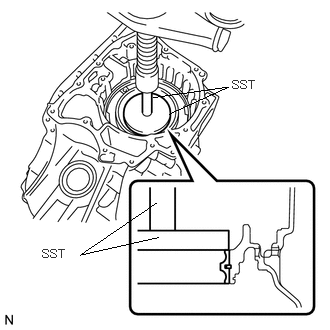
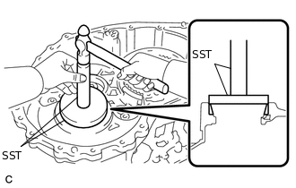
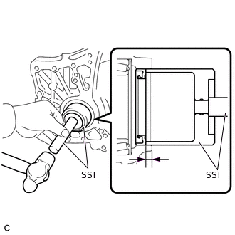
INSTALL COUNTER DRIVEN GEAR REAR TAPERED ROLLER BEARING OUTER RACE
-
Using SST and a hammer, install a new counter driven gear rear tapered roller bearing outer race to the transaxle case.
09950-60010
09951-00650
09950-70010
09951-07100
Note:Be sure to install the counter driven gear rear tapered roller bearing outer race so that there is no clearance between the bearing outer race and the transaxle case. If there is any clearance, the turning torque of the counter drive gear cannot be measured correctly.
-
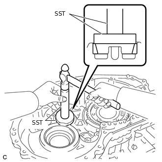
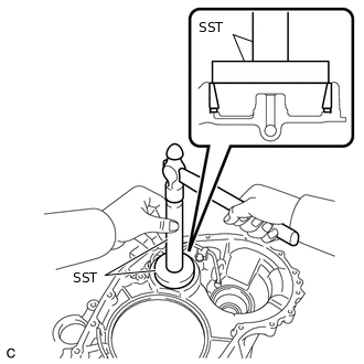
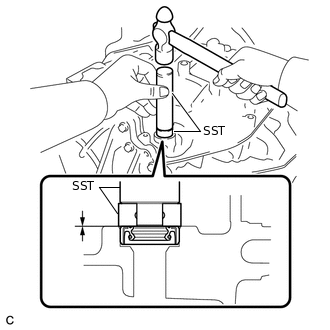
INSTALL FRONT DIFFERENTIAL CASE REAR TAPERED ROLLER BEARING OUTER RACE
-
Using SST and a hammer, tap in a new front differential case rear tapered roller bearing outer race to the transaxle case.
09950-60020
09951-00790
09950-70010
09951-07150
Note:Ensure that there is no clearance between the bearing and transaxle case.
-
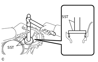
INSTALL COUNTER DRIVEN GEAR FRONT TAPERED ROLLER BEARING OUTER RACE
-
Install the shim to the transaxle housing.
Using SST, install a new counter driven gear front tapered roller bearing outer race to the transaxle housing.
09950-60020
09951-00810
09950-70010
09951-07100
Note:Be sure to install the counter driven gear front tapered roller bearing outer race so that there is no clearance between the shim and the transaxle housing.
-
INSTALL FRONT DIFFERENTIAL CASE FRONT TAPERED ROLLER BEARING OUTER RACE
Install the shim to the transaxle housing.
-
Using SST and a hammer, tap in a new front differential case front tapered roller bearing outer race to the transaxle housing.
09950-60010
09951-00480
09950-70010
09951-07150
Note:Ensure that there is no clearance between the bearing and transaxle housing.
INSTALL FRONT DIFFERENTIAL CASE REAR TAPERED ROLLER BEARING INNER RACE
-
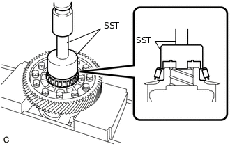
Using SST and a press, install a new front differential case rear tapered roller bearing inner race to the front differential case.
09726-36010
09950-70010
09951-07100
Note:Do not damage the front differential case rear tapered roller bearing inner race cage when installing the front differential case rear tapered roller bearing inner race.
Ensure that there is no clearance between the front differential case rear tapered roller bearing inner race and front differential case.
-
INSTALL FRONT DIFFERENTIAL CASE FRONT TAPERED ROLLER BEARING INNER RACE
-

Using SST and a press, install a new front differential case front tapered roller bearing inner race to the front differential case.
09316-12010
09649-17010
09950-70010
09951-07100
Note:Do not damage the front differential case front tapered roller bearing inner race cage when installing the front differential case front tapered roller bearing inner race.
Ensure that there is no clearance between the front differential case front tapered roller bearing inner race and front differential case.
-
ADJUST DIFFERENTIAL SIDE BEARING PRELOAD
Remove packing material from the contact surfaces between the transaxle housing and transaxle case.
-
Install the front differential case to the transaxle case.
-
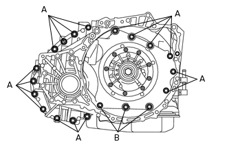
Install the transaxle housing to the transaxle case with the 20 bolts.
for Bolt A
22.7 N*m
231 kgf*cm
17 ft.*lbf
for Bolt B
30.6 N*m
312 kgf*cm
23 ft.*lbf
-
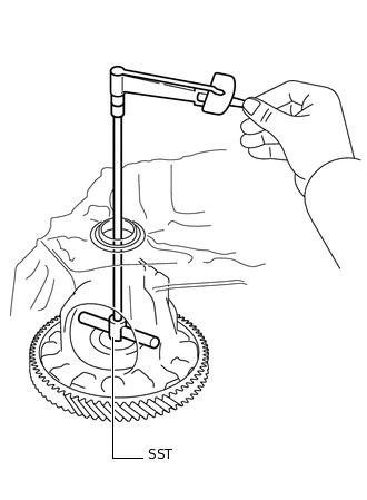
Using SST and a torque wrench, measure the turning torque of the differential side bearing while rotating SST at 10 rpm.
09564-33010
Turning torque
0.72 to 1.40 N*m (7.35 to 14.27 kgf*cm, 6.38 to 12.39 in.*lbf)
If the turning torque is not within the specified range, refer to the table below to select a shim so that the turning torque is within the specified range.
Table 1. Shim Thickness: Thickness
Thickness
Thickness
Thickness
2.000 mm (0.0787 in.)
2.225 mm (0.0876 in.)
2.450 mm (0.0965 in.)
2.675 mm (0.105 in.)
2.025 mm (0.0797 in.)
2.250 mm (0.0886 in.)
2.475 mm (0.0974 in.)
2.700 mm (0.106 in.)
2.050 mm (0.0807 in.)
2.275 mm (0.0896 in.)
2.500 mm (0.0984 in.)
2.725 mm (0.107 in.)
2.075 mm (0.0817 in.)
2.300 mm (0.0906 in.)
2.525 mm (0.0994 in.)
2.750 mm (0.108 in.)
2.100 mm (0.0827 in.)
2.325 mm (0.0915 in.)
2.550 mm (0.100 in.)
2.775 mm (0.109 in.)
2.125 mm (0.0837 in.)
2.350 mm (0.0925 in.)
2.575 mm (0.101 in.)
2.800 mm (0.110 in.)
2.150 mm (0.0846 in.)
2.375 mm (0.0935 in.)
2.600 mm (0.102 in.)
2.825 mm (0.111 in.)
2.175 mm (0.0856 in.)
2.400 mm (0.0945 in.)
2.625 mm (0.103 in.)
2.850 mm (0.112 in.)
2.200 mm (0.0866 in.)
2.425 mm (0.0955 in.)
2.650 mm (0.104 in.)
2.875 mm (0.113 in.)
-
Remove the 20 bolts and the transaxle housing from the transaxle case.
-
Remove the front differential case from the transaxle case.
INSTALL COUNTER DRIVEN GEAR FRONT TAPERED ROLLER BEARING
-
Using SST and a press, install a new counter driven gear front tapered roller bearing to the counter driven gear.
09950-60010
09951-00530
Note:Be sure to install the counter driven gear front tapered roller bearing so that there is no clearance between the bearing and the counter driven gear. If there is any clearance, the turning torque of the counter drive gear cannot be measured correctly.
-
INSTALL COUNTER DRIVEN GEAR REAR TAPERED ROLLER BEARING
-
Using SST and a press, install a new counter driven gear rear tapered roller bearing to the counter driven gear.
09950-60010
09951-00420
Note:Be sure to install the counter driven gear rear tapered roller bearing so that there is no clearance between each of them and the counter driven gear.
-
ADJUST COUNTER DRIVEN GEAR PRELOAD
-
Install the counter driven gear and front differential case to the transaxle case.
-
Install the transaxle housing to the transaxle case with the 20 bolts.
for Bolt A
22.7 N*m
231 kgf*cm
17 ft.*lbf
for Bolt B
30.6 N*m
312 kgf*cm
23 ft.*lbf
-
Using SST and a torque wrench, measure the turning torque of the counter driven gear while rotating SST at 10 rpm.
09564-33010
Turning torque
Differential side bearing preload + 2.38 to 4.69 N*m (24.28 to 47.82 kgf*cm, 21.07 to 41.50 in.*lbf)
If the turning torque is not within the specified range, refer to the table below to select a shim of the counter driven gear front tapered roller bearing outer race so that the turning torque is within the specified range.
Table 2. Shim Thickness: Thickness
Thickness
Thickness
Thickness
2.000 mm (0.0787 in.)
2.275 mm (0.0896 in.)
2.525 mm (0.0994 in.)
2.775 mm (0.109 in.)
2.025 mm (0.0797 in.)
2.300 mm (0.0906 in.)
2.550 mm (0.100 in.)
2.800 mm (0.110 in.)
2.050 mm (0.0807 in.)
2.325 mm (0.0915 in.)
2.575 mm (0.101 in.)
2.825 mm (0.111 in.)
2.075 mm (0.0817 in.)
2.350 mm (0.0925 in.)
2.600 mm (0.102 in.)
2.850 mm (0.112 in.)
2.100 mm (0.0827 in.)
2.375 mm (0.0935 in.)
2.625 mm (0.103 in.)
2.875 mm (0.113 in.)
2.125 mm (0.0837 in.)
2.400 mm (0.0945 in.)
2.650 mm (0.104 in.)
2.900 mm (0.114 in.)
2.150 mm (0.0846 in.)
2.425 mm (0.0955 in.)
2.675 mm (0.105 in.)
2.925 mm (0.115 in.)
2.175 mm (0.0856 in.)
2.450 mm (0.0965 in.)
2.700 mm (0.106 in.)
2.950 mm (0.116 in.)
2.200 mm (0.0866 in.)
2.475 mm (0.0974 in.)
2.725 mm (0.107 in.)
2.975 mm (0.117 in.)
2.225 mm (0.0876 in.)
2.500 mm (0.0984 in.)
2.750 mm (0.108 in.)
3.000 mm (0.118 in.)
2.250 mm (0.0886 in.)
-
-
-
-
Remove the 20 bolts and the transaxle housing from the transaxle case.
-
Remove the counter driven gear and front differential case from the transaxle case.
-
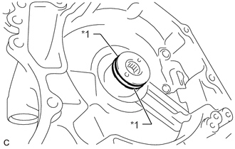
INSTALL TRANSAXLE CASE OIL SEAL LH
Coat the lip of a new transaxle case oil seal LH with MP grease.
-
Using SST and a hammer, tap in a new transaxle case oil seal LH.
09316-10010
09950-70010
09951-07100
Standard depth
-0.5 to 0.5 mm (-0.0197 to 0.0197 in.)
Note:Make sure that the transaxle oil seal LH is installed in the correct direction.
INSTALL TRANSAXLE CASE OIL SEAL RH (OUTER)
Coat the lip of a new transaxle case oil seal RH (outer) with MP grease.
-
Using SST and a hammer, tap in the transaxle case oil seal RH (outer).
09649-17010
09950-70010
09951-07200
Standard depth
5.5 to 6.5 mm (0.217 to 0.255 in.)
Note:Make sure that the transaxle case oil seal RH (outer) is installed in the correct direction.
INSTALL MANUAL VALVE LEVER SHAFT OIL SEAL
-
Coat the lip of a new manual valve lever shaft oil seal with MP grease.
Using SST and a hammer, install the manual valve lever shaft oil seal to the transaxle case.
09950-60010
09951-00230
09950-70010
09951-07100
Oil seal driven in depth
-0.5 to 0.5 mm (-0.0197 to 0.0197 in.)
-
INSTALL MANUAL VALVE LEVER SHAFT SUB-ASSEMBLY
-
Install the manual valve lever shaft sub-assembly to the transaxle case.
Note:Do not damage the manual valve lever shaft oil seal while installing the manual valve lever shaft sub-assembly to the transaxle case.
-
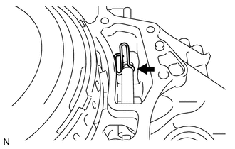
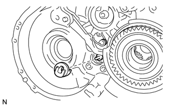
Using needle-nose pliers, install the manual valve shaft retainer spring to the transaxle case.
-
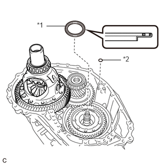
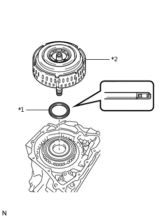
INSTALL PARKING LOCK ROD SUB-ASSEMBLY
-
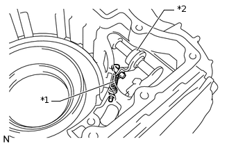
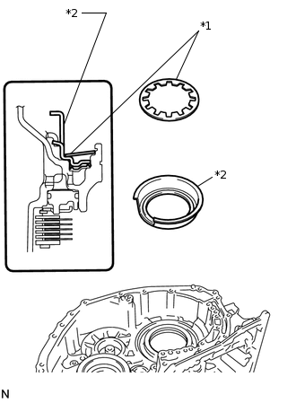
*1
Parking Lock Rod Sub-assembly
*2
Manual Valve Lever Shaft Sub-assembly
Align the slot with the notches on the manual valve lever shaft sub-assembly and install the parking lock rod sub-assembly.
-
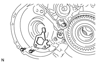
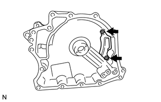
INSTALL MANUAL DETENT SPRING SUB-ASSEMBLY
-
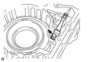
Install the manual detent spring sub-assembly and cover to the transaxle case with the bolt.
22.7 N*m
231 kgf*cm
17 ft.*lbf
Note:Make sure to install the manual detent spring sub-assembly first and then the cover.
-
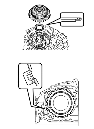
INSTALL NO. 3 BRAKE PISTON
-
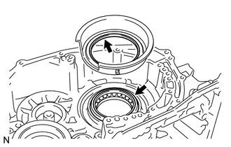
Coat the contact surface of the transaxle case with ATF.
Coat the lip of the No. 3 brake piston with ATF.
-
Temporarily install the pawl stopper plate to the transaxle case with the 2 bolts.
Press the No. 3 brake piston into the transaxle case.
Note:Make sure that the lip of the No. 3 brake piston is not twisted and does not get caught in the transaxle case.
After installation, make sure that the protrusions on the No. 3 brake piston and the grooves on the pawl stopper plate are aligned.
Tip:Use the installation surface of the brake piston return spring to press the No. 3 brake piston into the transaxle case.
-
*1
Brake Piston Return Spring
*2
No. 3 Brake Piston
Install the brake piston return spring to the transaxle case.
Remove the 2 bolts and pawl stopper plate from the transaxle case.
-
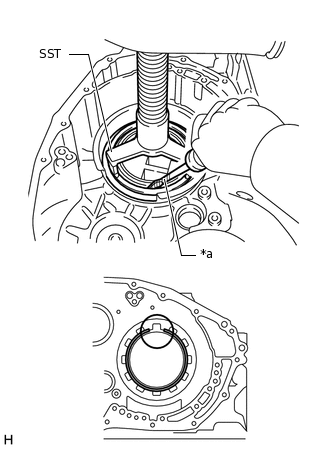
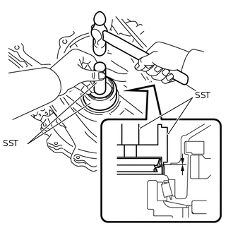
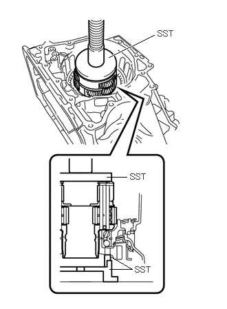
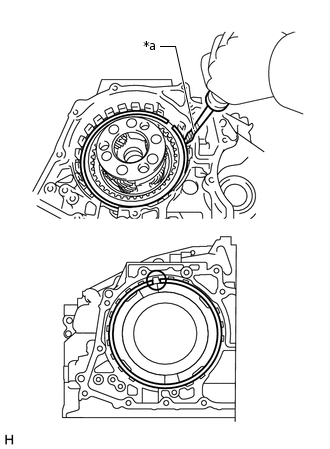
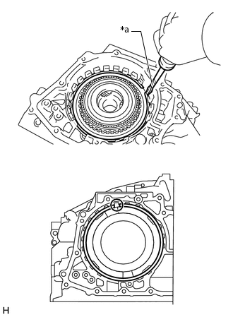
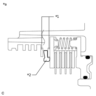
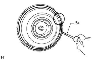
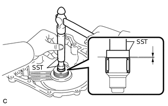
*a
Protective Tape
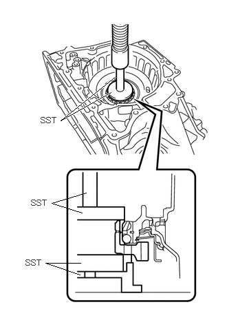
Place SST on the brake piston return spring and compress the brake piston return spring using a press.
09387-00070
Note:Stop the press when the brake piston return spring is flush with the snap ring groove. This prevents the brake piston return spring from being deformed.
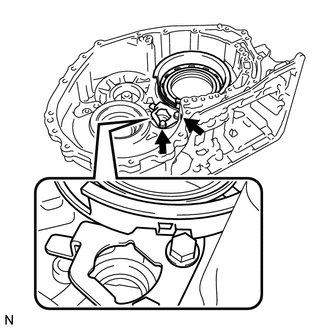
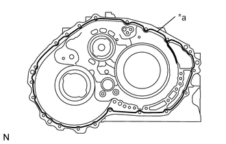
Using a screwdriver, install the snap ring to the transaxle case as shown in the illustration.
Note:Confirm that the snap ring is correctly located in the groove of the transaxle case.
Be sure to align the opening of the snap ring with one of the protrusions on the brake piston return spring as shown in the illustration.
Be careful not to damage the transaxle case.
Tip:Tape the screwdriver tip before use.
-
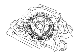
INSTALL COUNTER DRIVE GEAR
Install 2 new balls of the counter drive gear bearing to the counter drive gear bearing.
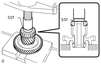
-
Using SST, install the counter drive gear, a new bearing inner race (front side) and new bearing inner race (rear side) to the transaxle case.
09223-15030
09527-17011
09950-70010
09951-07100
09950-60020
09951-00810
Note:There should not be any clearance between the bearing inner race (front side) and counter drive gear.
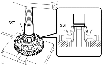
INSTALL FRONT PLANETARY GEAR ASSEMBLY
-
Using SST and a press, press the front planetary gear assembly onto the transaxle case.
09223-15030
09527-17011
09951-01100
-
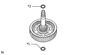
INSTALL NO. 2 BRAKE PISTON
-
*1
O-ring
Coat 2 new O-rings with ATF and install them to the No. 2 brake piston.
Note:Ensure that the 2 O-rings are not twisted.
-
Install the No. 2 brake piston to the transaxle case.
Note:Be careful not to damage the O-rings.
-
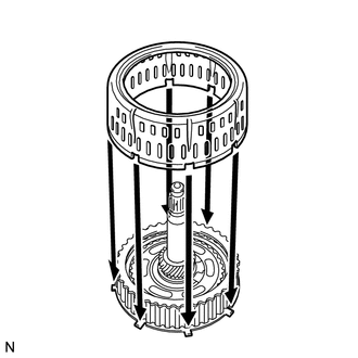
INSTALL 1ST AND REVERSE BRAKE RETURN SPRING SUB-ASSEMBLY
Install the 1st and reverse brake return spring sub-assembly to the transaxle case.
Place SST on the 1st and reverse brake return spring sub-assembly and compress the 1st and reverse brake return spring sub-assembly using a press.
09387-00060
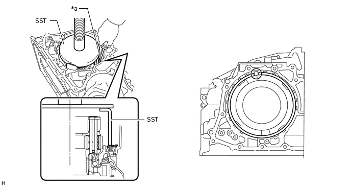
*a
Protective Tape
-
-
Note:Stop the press when the 1st and reverse brake return spring sub-assembly is flush with the snap ring groove. This prevents the 1st and reverse brake return spring sub-assembly from being deformed.
Using a screwdriver, install the snap ring to the transaxle case as shown in the illustration.
Note:Confirm that the snap ring is correctly located in the groove of the transaxle case.
Be sure to align the opening of the snap ring with one of the protrusions on the transaxle case as shown in the illustration.
Be careful not to damage the transaxle case.
Tip:Tape the screwdriver tip before use.
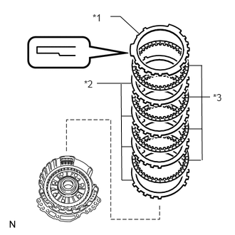
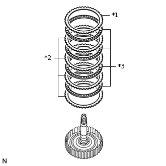
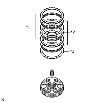
INSTALL NO. 2 BRAKE DISC
-
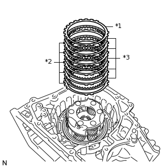
*1
No. 2 Brake Flange
*2
No. 2 Brake Plate
*3
No. 2 Brake Disc
Install the 5 No. 2 brake discs, 5 No. 2 brake plates and No. 2 brake flange to the transaxle case.
Note:Make sure that the discs, plates and flange are installed in the correct order.
-
*a
Protective Tape
Using a screwdriver, install the snap ring to the transaxle case.
Note:Confirm that the snap ring is correctly located in the groove of the transaxle case.
Be sure to align the opening of the snap ring with one of the protrusions on the transaxle case as shown in the illustration.
Be careful not to damage the transaxle case.
Tip:Tape the screwdriver tip before use.
-
INSPECT CLEARANCE OF NO. 2 BRAKE
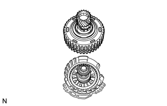
INSTALL PLANETARY RING GEAR FLANGE
-
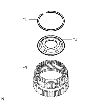
*1
Snap Ring
*2
Planetary Ring Gear Flange
*3
Planetary Ring Gear
Install the planetary ring gear flange to the planetary ring gear.
Using a screwdriver, install the snap ring to the planetary ring gear.
Note:Confirm that the snap ring is correctly located in the groove of the planetary ring gear.
Be careful not to damage the planetary ring gear.
Tip:Tape the screwdriver tip before use.
-
INSTALL PLANETARY RING GEAR
-
*1
One-way Clutch Assembly
*2
Outer Race Retainer
*3
Planetary Ring Gear
Install the outer race retainer to the one-way clutch assembly.
Install the planetary ring gear to the one-way clutch assembly.
Note:Make sure that the one-way clutch assembly is positioned in the correct direction as shown in the illustration.
-
INSTALL ONE-WAY CLUTCH ASSEMBLY
-
Coat the thrust needle roller bearing with ATF, and install it onto the planetary gear assembly.
Table 3. Bearing Diameter: -
Inside
Outside
Bearing
56.1 mm (2.21 in.)
80.9 mm (3.19 in.)
Note:Be sure to install the thrust needle roller bearing properly so that the temper colored side of the race will be visible.
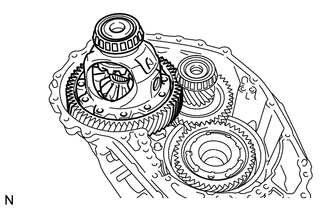
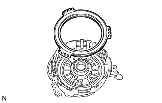
Install the one-way clutch assembly to the transaxle case.
Note:Make sure that there is no clearance between the retainer and the claw on the one-way clutch assembly. If there is any clearance, the spring of the retainer will be deformed.
-
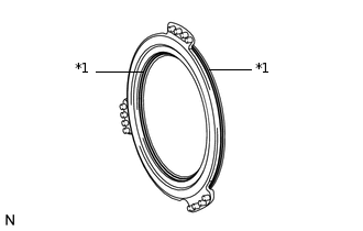
*a
Protective Tape
Using a screwdriver, install the snap ring to the transaxle case.
Note:Confirm that the snap ring is correctly located in the groove of the transaxle case.
Be sure to align the opening of the snap ring with one of the protrusions on the transaxle case as shown in the illustration.
Be careful not to damage the transaxle case.
Tip:Tape the screwdriver tip before use.
-
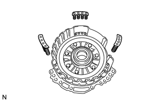
INSTALL PARKING LOCK PAWL
-
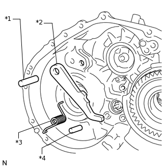
*1
Parking Lock Pawl Shaft
*2
Parking Lock Pawl
*3
Spring
*4
Parking Lock Pawl Pin
Install the parking lock pawl to the transaxle case with the parking lock pawl shaft.
Install the parking lock pawl pin to the transaxle case.
-
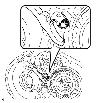
Install the spring to the parking lock pawl.
Note:Make sure that one end of the spring is set in the hole of the transaxle case and the other end is positioned on the parking lock pawl as shown in the illustration.
-
INSTALL PARKING LOCK SLEEVE
-
Install the parking lock sleeve to the transaxle case.
-
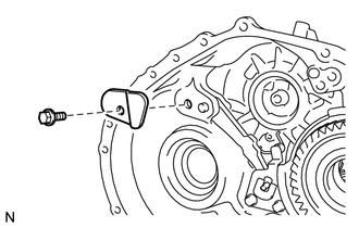
INSTALL PAWL STOPPER PLATE
-
Install the pawl stopper plate to the transaxle case with the 2 bolts.
22.7 N*m
231 kgf*cm
17 ft.*lbf
-
INSTALL PAWL SHAFT CLAMP
-
Install the pawl shaft clamp to the transaxle case with the bolt.
22.7 N*m
231 kgf*cm
17 ft.*lbf
-
INSTALL COUNTER DRIVEN GEAR
-
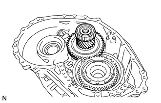
Install the counter driven gear to the transaxle case.
-
INSTALL COUNTER DRIVE GEAR NUT
-
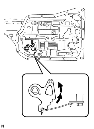
Turn the manual valve lever 2 notches counterclockwise to set it to P as shown in the illustration.
-
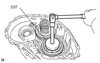
Using SST, install a new counter drive gear nut.
09387-00130
120 N*m
1224 kgf*cm
89 ft.*lbf
-
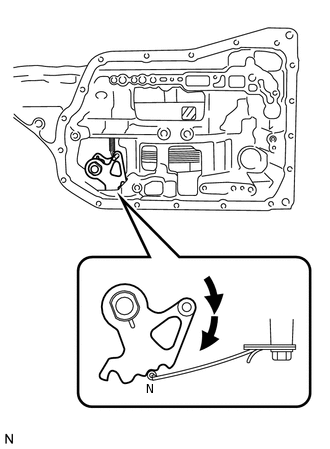
Turn the manual valve lever 2 notches clockwise to set it to N as shown in the illustration.
-
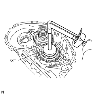
Using SST and a torque wrench, measure the turning torque of the bearing while rotating SST at 60 rpm.
09387-00130
Turning torque
0.1 to 0.2 N*m (1 to 2 kgf*cm, 0.9 to 1.9 in.*lbf)
If the measured value is not within the specified range, gradually tighten the nut until the turning torque falls within the specified range.
Maximum torque
180 N*m (1835 kgf*cm, 133 ft.*lbf)
Using a chisel and hammer, securely stake the counter drive gear nut.
-
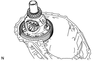
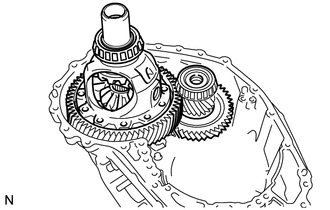
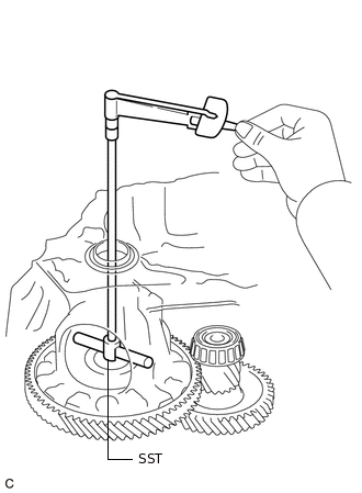
INSPECT FRONT DIFFERENTIAL PINION BACKLASH
INSTALL FRONT DIFFERENTIAL CASE
-
Install the front differential case to the transaxle case.
-
INSTALL NO. 1 BRAKE PISTON
-
*1
O-ring
Coat 2 new O-rings with ATF and install them to the No. 1 brake piston.
Note:Ensure that the O-rings are not twisted.
-
Install the No. 1 brake piston to the oil pump assembly.
Note:Be careful not to damage the O-rings.
-
INSTALL 2ND BRAKE PISTON RETURN SPRING SUB-ASSEMBLY
-
Install the 3 2nd brake piston return springs to the oil pump assembly.
Note:Make sure that the 3 2nd brake piston return springs are installed onto the protrusions on the oil pump assembly.
-
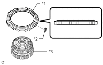
INSTALL NO. 1 BRAKE DISC
-
*1
No. 1 Brake Flange
*2
No. 1 Brake Plate
*3
No. 1 Brake Disc
Install the 4 No. 1 brake discs, 4 No. 1 brake plates and No. 1 brake flange to the oil pump assembly.
Note:Make sure that the discs, plates, and flange are installed in the correct order.
Be sure to install the flange in the correct direction.
Place SST on the flange and compress the flange using a press.
09387-00070
09495-65040
Note:Stop the press when the brake piston return spring is flush with the snap ring groove. This prevents the brake piston return spring from being deformed.
-
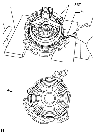
*a
Protective Tape
Using a screwdriver, install the snap ring to the oil pump assembly as shown in the illustration (#1).
Note:Confirm that the snap ring is correctly located in the groove of the oil pump.
Make sure to align the protruding part of the snap ring with the indented part (#1) of the oil pump assembly shown in the illustration to install the snap ring.
Be careful not to damage the oil pump assembly.
Tip:Tape the screwdriver tip before use.
-
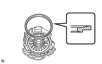
Install the brake snap ring stopper to the oil pump assembly.
Note:Be sure to install the brake snap ring stopper in the correct direction.
-
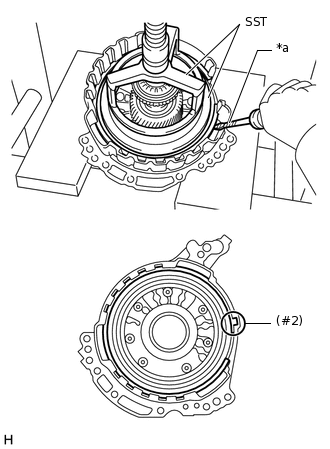
*a
Protective Tape
Using a screwdriver, install the snap ring to the oil pump assembly as shown in the illustration (#2).
Note:Confirm that the snap ring is correctly located in the groove of the oil pump assembly.
Make sure to align the protruding part of the snap ring with the indented part (#2) of the oil pump assembly shown in the illustration to install the snap ring.
Be careful not to damage the oil pump assembly.
Tip:Tape the screwdriver tip before use.
-
*1
Snap Ring
*2
Brake Snap Ring Stopper
*a
Correctly installed
Check that the brake snap ring stopper can be turned by hand.
Note:If the brake snap ring stopper cannot be turned by hand, the brake snap ring stopper may have been installed upside down, or the snap ring may not have been completely located in the groove on the oil pump. Remove and reinstall the snap ring and the brake snap ring stopper.
-
INSPECT CLEARANCE OF NO. 1 BRAKE
INSTALL UNDERDRIVE PLANETARY SUN GEAR
-
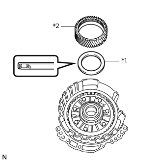
*1
Thrust Needle Roller Bearing
*2
Underdrive Planetary Sun Gear
Coat the thrust needle roller bearing with ATF, and install it to the oil pump assembly.
Table 4. Bearing Diameter: -
Inside
Outside
Bearing
57.7 mm (2.27 in.)
75.2 mm (2.96 in.)
Note:Be sure to install the thrust needle roller bearing properly so that the temper colored side of the race will be visible.
Install the underdrive planetary sun gear to the oil pump assembly.
-
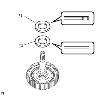
INSTALL INPUT SHAFT SUB-ASSEMBLY
-
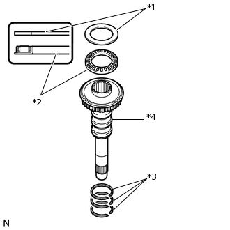
*1
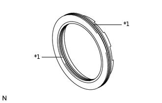
Thrust Needle Roller Race
*2
Thrust Needle Roller Bearing
*3
Input Shaft Oil Seal Ring
*4
Input Shaft Sub-assembly
Coat 3 new input shaft oil seal rings with ATF and install them to the input shaft sub-assembly.
Note:Do not expand the gap of the oil seal ring excessively.
Coat the thrust needle roller bearing and thrust needle roller race with ATF, and install them on the oil pump assembly.
Table 5. Bearing and Race Diameter: -
Inside
Outside
Bearing
29.1 mm (1.15 in.)
48.6 mm (1.91 in.)
Race
30.7 mm (1.21 in.)
48.3 mm (1.90 in.)
Note:Be sure to install the thrust needle roller bearing in the correct direction.
-
Install the input shaft sub-assembly to the oil pump assembly.
-
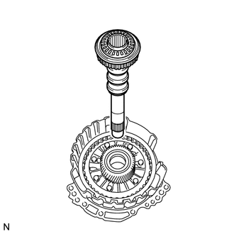
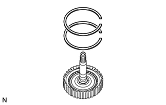
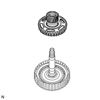
INSTALL PLANETARY SUN GEAR SUB-ASSEMBLY
-
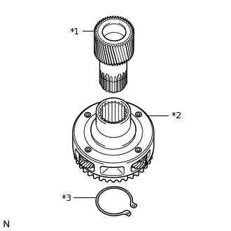
*1
Planetary Sun Gear Sub-assembly
*2
Underdrive Planetary Gear Assembly
*3
Snap Ring
Using a snap ring expander, install the snap ring to the underdrive planetary gear assembly.
Using a snap ring expander, install the planetary sun gear sub-assembly to the underdrive planetary gear assembly with the snap ring expanded.
-
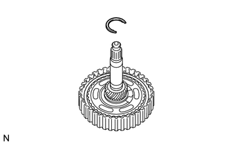
INSTALL UNDERDRIVE PLANETARY RING GEAR
-
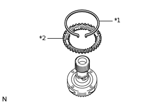
*1
Snap Ring
*2
Underdrive Planetary Ring Gear
Install the underdrive planetary ring gear to the underdrive planetary gear assembly.
Using needle-nose pliers, install the snap ring to the underdrive planetary ring gear.
Note:Confirm that the snap ring is correctly located in the groove of the underdrive planetary ring gear.
-
INSTALL NO. 3 BRAKE HUB
-
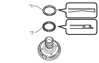
*1
Thrust Needle Roller Race
*2
Thrust Needle Roller Bearing
Coat the thrust needle roller bearing and thrust needle roller race with ATF and install them to the underdrive planetary gear assembly.
Table 6. Thrust Needle Roller Bearing and Thrust Needle Roller Race Diameter: -
Inside
Outside
Thrust needle roller bearing
62.6 mm (2.46 in.)
82.9 mm (3.26 in.)
Thrust needle roller race
65.9 mm (2.59 in.)
80.3 mm (3.16 in.)
Note:Be sure to install the thrust needle roller bearing so that the temper colored side of the race is visible.
-
Install the No. 3 brake hub to the underdrive planetary gear assembly.
-
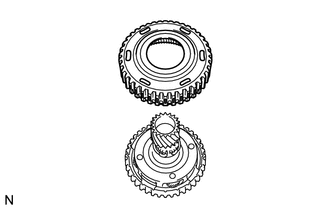
INSTALL UNDERDRIVE PLANETARY GEAR ASSEMBLY
-
Install the underdrive planetary gear assembly to the oil pump assembly.
-
INSTALL NO. 3 BRAKE DISC
-
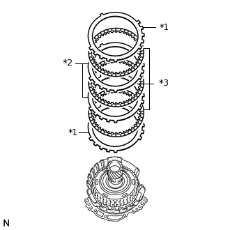
*1
No. 3 Brake Flange
*2
No. 3 Brake Plate
*3
No. 3 Brake Disc
Install the 2 No. 3 brake flanges, 3 No. 3 brake discs and 2 No. 3 brake plates to the oil pump assembly.
Note:Make sure that the discs, plates and flanges are installed in the correct order.
-
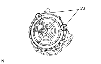
Using a screwdriver, install the snap ring to the oil pump assembly.
Note:Confirm that the snap ring is correctly located in the groove of the oil pump assembly.
Make sure that the snap ring ends are positioned as shown in the illustration (A).
Be careful not to damage the oil pump assembly.
Tip:Tape the screwdriver tip before use.
-
INSPECT CLEARANCE OF NO. 3 BRAKE
INSTALL FRONT OIL PUMP BODY O-RING
-
Coat a new O-ring with ATF and install it to the front oil pump body sub-assembly.
-
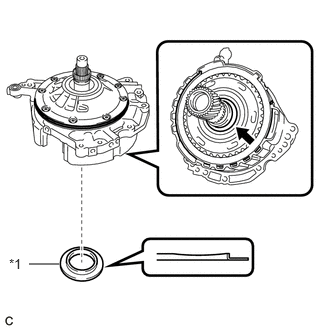
INSTALL OIL PUMP ASSEMBLY
-
*1
Thrust Needle Roller Bearing
*2
O-ring
Coat a new O-ring with ATF and install it to the transaxle case.
Coat the thrust needle roller bearing with ATF.
Install the thrust needle roller bearing to the counter drive gear nut.
Table 7. Thrust Needle Roller Bearing Diameter: -
Inside
Outside
Thrust needle roller bearing
53.1 mm (2.09 in.)
79 mm (3.11 in.)
Note:Be sure to install the thrust needle roller bearing so that the temper colored side of the race is visible.
Coat the thrust needle roller race with MP grease.
-
*1
Thrust Needle Roller Race
Install the thrust needle roller race to the underdrive planetary gear assembly.
Table 8. Thrust Needle Roller Race Diameter: -
Inside
Outside
Thrust needle roller race
59.4 mm (2.34 in.)
77 mm (3.03 in.)
-
*1
Gasket
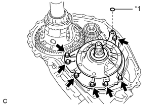
Coat a new gasket with ATF and install it to the oil pump assembly.
Install the oil pump assembly to the transaxle case with the 7 bolts.
22.7 N*m
231 kgf*cm
17 ft.*lbf
-
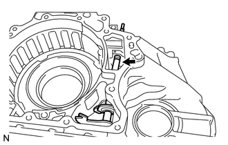
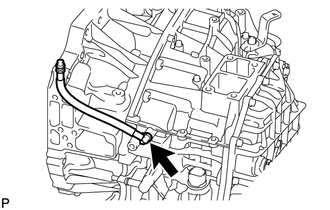
INSTALL DIFFERENTIAL GEAR LUBE APPLY TUBE
-
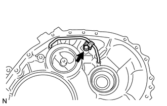
Install the differential gear lube apply tube to the transaxle housing.
Note:Insert the differential gear lube apply tube into the transaxle case until it makes contact with the stopper.
Install the clamp to the differential gear lube apply tube with the bolt.
22.7 N*m
231 kgf*cm
17 ft.*lbf
Note:There should be clearance between the differential lube apply tube and clamp.
-
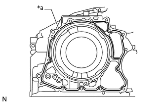
INSTALL TRANSAXLE HOUSING
Clean and degrease the contact surfaces between the transaxle housing and transaxle case.
Note:Make sure that there is no ATF on the contact surfaces.
-
*a
Seal Packing
Apply seal packing to the transaxle case.
Seal packing
Toyota Genuine Seal Packing 1281, Three Bond 1281 or equivalent
Note:Apply seal packing in a continuous line (width 1.2 mm (0.0472 in.)) along the sealing surface.
After applying seal packing, install the transaxle housing to the transaxle case within 3 minutes and tighten the bolts within 10 minutes.
-
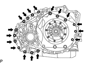
Install the transaxle housing to the transaxle case with the 17 bolts.
30.6 N*m
312 kgf*cm
23 ft.*lbf
-
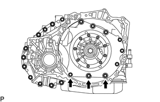
Clean and degrease the 3 bolts and the installation holes in the transaxle case.
Apply adhesive to 2 or 3 threads on the ends of the 3 bolts.
Adhesive
Toyota Genuine Adhesive 1324, Three Bond 1324 or equivalent
Install the 3 bolts.
22.7 N*m
231 kgf*cm
17 ft.*lbf
INSTALL NO. 1 CLUTCH DISC
-
*1
No. 1 Clutch Flange
*2
No. 1 Clutch Plate
*3
No. 1 Clutch Disc
Install the No. 1 clutch flange, 4 No. 1 clutch discs and 4 No. 1 clutch plates to the direct multiple disc clutch assembly.
Note:Make sure that the flange, discs and plates are installed in the correct order.
-
Using a screwdriver, install the 2 snap rings to the direct multiple disc clutch assembly.
Note:Confirm that the snap rings are correctly located in the groove of the direct multiple disc clutch assembly.
Be careful not to damage the direct multiple disc clutch assembly.
Tip:Tape the screwdriver tip before use.
-
INSPECT CLEARANCE OF NO. 1 CLUTCH DISC
INSTALL REAR PLANETARY SUN GEAR ASSEMBLY
-
*1
Thrust Needle Roller Bearing
*2
Thrust Needle Roller Race
Coat the thrust needle roller bearing and thrust needle roller race with ATF, and install them to the direct multiple disc clutch assembly.
Table 9. Bearing and Race Diameter: -
Inside
Outside
Bearing
28 mm (1.10 in.)
47.1 mm (1.85 in.)
Race
26.1 mm (1.03 in.)
44 mm (1.73 in.)
Note:Install the thrust needle roller bearing properly so that the temper colored side of the race will be visible.
-
Install the rear planetary sun gear assembly to the direct multiple disc clutch assembly.
-
Using a snap ring expander, install the snap ring to the direct multiple disc clutch assembly.
-
INSTALL NO. 2 CLUTCH DISC
-
*1
No. 2 Clutch Plate
*2
No. 2 Clutch Disc
*3
No. 2 Clutch Flange
Install the No. 2 clutch flange, 3 No. 2 clutch discs and 3 No. 2 clutch plates to the direct multiple disc clutch assembly.
Note:Make sure that the flange, discs and plates are installed in the correct order.
-
INSTALL DIRECT MULTIPLE DISC CLUTCH SNAP RING
-
*1
Intermediate Shaft Oil Seal
*2
O-ring
Coat a new O-ring with ATF and install it to the direct multiple disc clutch assembly.
Coat a new intermediate shaft oil seal with ATF and install it to the direct multiple disc clutch assembly.
-
Install the No. 2 direct clutch piston to the direct multiple disc clutch assembly.
Note:Be sure to engage the claws on the direct multiple disc clutch assembly in the grooves on the No. 2 direct clutch piston.
-
*a
Protective Tape
Using a screwdriver, install the snap ring to the direct multiple disc clutch assembly.
Note:Position the opening of the snap ring as shown in the illustration.
Confirm that the snap ring is correctly located in the groove of the direct multiple disc clutch assembly.
Be careful not to damage the direct multiple disc clutch assembly.
Tip:Tape the screwdriver tip before use.
-
INSPECT CLEARANCE OF NO. 2 CLUTCH DISC
INSTALL DIRECT MULTIPLE DISC CLUTCH ASSEMBLY
-
*1
Thrust Needle Roller Bearing
*2
Direct Multiple Disc Clutch Assembly
Coat the thrust needle roller bearing with ATF and install it on the transaxle case.
Table 10. Bearing Diameter: -
Inside
Outside
Bearing
61.2 mm (2.41 in.)
79 mm (3.11 in.)
Install the direct multiple disc clutch assembly to the transaxle case.
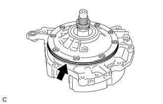
Clean the contact surfaces of the transaxle case and rear transaxle cover sub-assembly.
-
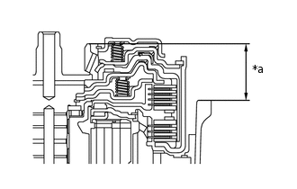
*a
Dimension A
As shown in the illustration, place a straightedge on the multiple direct clutch drum and measure the distance between the transaxle case and the straightedge using a vernier caliper (Dimension A).
-
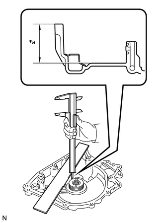
*a
Dimension B
Using a vernier caliper and a straightedge, measure the distance shown in the illustration (Dimension B).
Calculate the end play value using the following formula:
End play = Dimension B - Dimension A - Thrust needle roller bearing thickness
End play
0.007 to 1.113 mm (0.000276 to 0.0438 in.)
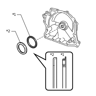
-
INSTALL REAR TRANSAXLE COVER SUB-ASSEMBLY
-
Using SST and a hammer, install a new needle roller bearing into the rear transaxle cover sub-assembly.
09950-60010
09951-00220
09950-70010
09951-07100
Installation depth
21.5 to 21.9 mm (0.847 to 0862 in.)
Clean and degrease the 2 "TORX" screws and the installation holes in the rear transaxle cover sub-assembly.
Apply adhesive to 2 or 3 threads on the ends of the 2 "TORX" screws.
Adhesive
Toyota Genuine Adhesive 1324, Three Bond 1324 or equivalent
-
Using a T30 "TORX" socket wrench, install the rear transaxle cover plate to the rear transaxle cover sub-assembly with the 2 "TORX" screws.
7.5 N*m
76 kgf*cm
66 in.*lbf
-
*1
Oil Seal Ring
Coat 2 new oil seal rings with ATF and install them to the rear transaxle cover sub-assembly.
Note:Confirm that the 2 oil seal rings are correctly located in the grooves of the rear transaxle cover sub-assembly.
-
*1
Thrust Needle Roller Bearing
*2
Thrust Needle Roller Race
Coat the thrust needle roller bearing and thrust needle roller race with MP grease and install them on the rear transaxle cover sub-assembly.
Table 11. Thrust Needle Roller Bearing and Thrust Needle Roller Race Diameter: -
Inside
Outside
Thrust needle roller bearing
48.9 mm (1.93 in.)
72.0 mm (2.84 in.)
Thrust needle roller race
52.2 mm (2.06 in.)
70.4 mm (2.77 in.)
-
Coat 3 new O-rings with ATF and install them to the transaxle case.
Note:Ensure that the O-rings are not twisted.
Remove packing material from the contact surfaces between the rear transaxle cover sub-assembly and transaxle case.
Note:Make sure that there is no ATF on the contact surfaces.
-
*a
Seal Packing
Apply seal packing to the transaxle case.
Seal packing
Toyota Genuine Seal Packing 1281, Three Bond 1281 or equivalent
Note:Apply seal packing in a continuous line (width 1.2 mm (0.0472 in.)) along the sealing surface.
After applying seal packing, install the rear transaxle cover sub-assembly to the transaxle case within 3 minutes and tighten the bolts within 10 minutes.
-
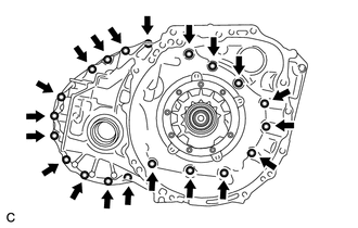
Install the rear transaxle cover sub-assembly to the transaxle case with the 12 bolts.
for bolt A
22.7 N*m
231 kgf*cm
17 ft.*lbf
-
Clean and degrease the 2 bolts and the installation holes in the transaxle case.
Apply adhesive to 2 or 3 threads on the ends of the 2 bolts labeled B.
Adhesive
Toyota Genuine Adhesive 1324, Three Bond 1324 or equivalent
Install the 2 bolts.
for bolt B
16.9 N*m
172 kgf*cm
12 ft.*lbf
-
Install a new gasket to the refill plug.
Install the refill plug to the rear transaxle cover sub-assembly.
49 N*m
500 kgf*cm
36 ft.*lbf
-
INSPECT INPUT SHAFT END PLAY
INSTALL TRANSAXLE CASE GASKET
-
Coat 2 new gaskets with ATF and install them to the transaxle case.
-
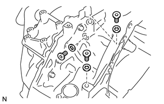
INSTALL TRANSMISSION VALVE BODY ASSEMBLY
Coat the O-ring of the transmission wire with ATF.
-
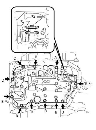
*1
Manual Valve Lever Shaft Sub-assembly Pin
*2
Manual Valve
*a
Positioning Bolt
Insert the manual valve lever shaft sub-assembly pin into the groove on the end of the manual valve as shown in the illustration and temporarily install the transmission valve body assembly to the transaxle case with the 11 bolts.
Item
Item
Bolt Length
Bolt Length
Bolt A
25 mm (0.984 in.)
Bolt B
30 mm (1.18 in.)
Bolt C
35 mm (1.38 in.)
Bolt D
45 mm (1.77 in.)
Bolt E
55 mm (2.17 in.)
Note:When installing the transmission valve body assembly, be careful not to allow the transmission revolution sensor and transaxle case to interfere with each other.
Be sure to insert the manual valve lever shaft sub-assembly pin into the groove on the end of the manual valve.
Tighten the 2 positioning bolts shown in the illustration.
10.8 N*m
110 kgf*cm
8 ft.*lbf
Tighten the 9 bolts to install the transmission valve body assembly.
10.8 N*m
110 kgf*cm
8 ft.*lbf
INSTALL VALVE BODY OIL STRAINER ASSEMBLY
-
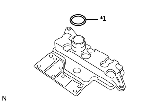
*1
O-ring
Coat a new O-ring with ATF and install it to the valve body oil strainer assembly.
Note:Ensure that the O-ring is not twisted or pinched.
-
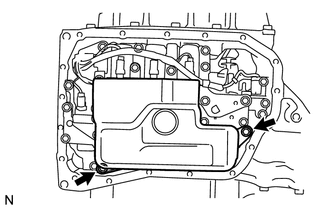
Install the valve body oil strainer assembly to the transmission valve body assembly with the 2 bolts.
10.8 N*m
110 kgf*cm
8 ft.*lbf
-
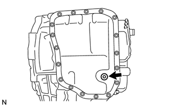
INSTALL AUTOMATIC TRANSAXLE OIL PAN SUB-ASSEMBLY
-
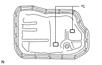
*1
Transmission Oil Cleaner Magnet
Install the 2 transmission oil cleaner magnets in the automatic transaxle oil pan sub-assembly.
Install a new gasket to the automatic transaxle oil pan sub-assembly.
-
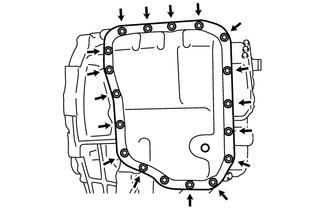
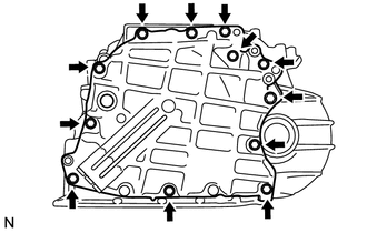
Install the automatic transaxle oil pan sub-assembly to the automatic transaxle assembly with the 17 bolts.
7.5 N*m
76 kgf*cm
66 in.*lbf
-
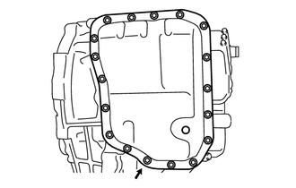
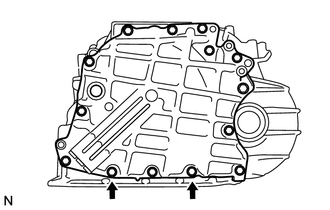
Clean and degrease the bolt and the installation hole in the automatic transaxle.
Apply adhesive to the bolt.
Adhesive
Toyota Genuine Adhesive 1344, Three Bond 1344 or equivalent
Install the bolt.
7.0 N*m
71 kgf*cm
62 in.*lbf
Note:In order to ensure proper sealing of the transmission oil pan bolts, apply adhesive to the bolts and install them within 10 minutes of adhesive application.
Completely remove any oil or grease from the contact surface of the transaxle case and automatic transaxle oil pan sub-assembly with the gasket before installation.
-
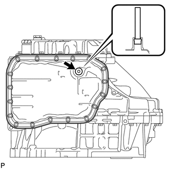
Using a 6 mm hexagon socket wrench, install the No. 1 transmission oil filler tube to the automatic transaxle assembly.
1.7 N*m
17 kgf*cm
15 in.*lbf
-
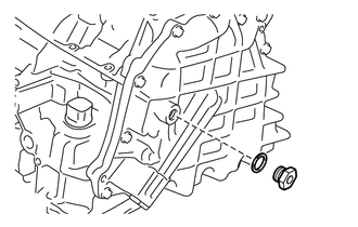
Using a 6 mm hexagon socket wrench, install the overflow plug and a new gasket to the automatic transaxle oil pan sub-assembly.
40 N*m
408 kgf*cm
30 ft.*lbf
-
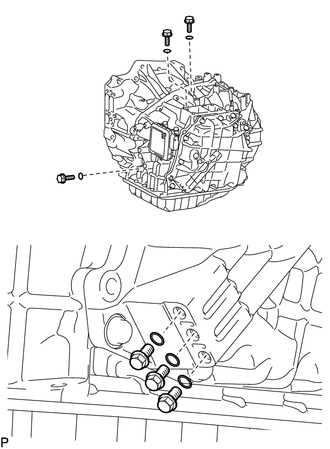
INSTALL TRANSAXLE CASE PLUG
Install 3 new gaskets to the 3 hexagon bolts.
Apply adhesive to the 3 hexagon bolts.
Adhesive
Toyota Genuine Seal Packing 1344, Three Bond 1344 or equivalent
Note:In order to ensure proper sealing of the hexagon bolts, apply adhesive to the bolts and install them within 10 minutes of adhesive application.
-
Using a 6 mm hexagon socket wrench, install the 3 hexagon bolts to the transaxle housing with the gaskets.
17 N*m
173 kgf*cm
13 ft.*lbf
-
Coat 6 new O-rings with ATF and install them to the 6 transaxle case plugs.
Install the 6 transaxle case plugs to the transaxle case and rear transaxle cover sub-assembly.
7.4 N*m
75 kgf*cm
65 in.*lbf
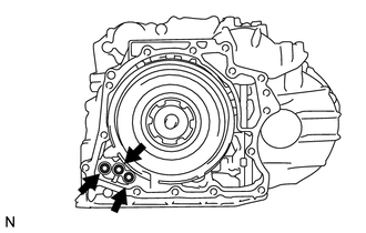
INSTALL OIL COOLER TUBE UNION
-
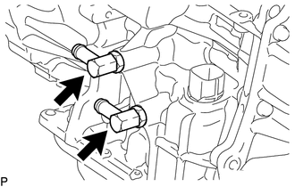
Coat 2 new O-rings with ATF and install them to the 2 oil cooler tube unions.
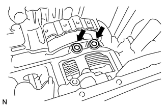
Using a 19 mm union nut wrench, install the 2 oil cooler tube unions as shown in the illustration.
27 N*m
275 kgf*cm
20 ft.*lbf
Note:Use the formula to calculate special torque values for situations where a union nut wrench is combined with a torque wrench (Click hereClick here).
-
INSTALL PARK/NEUTRAL POSITION SWITCH ASSEMBLY
-
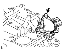
Temporarily install the park/neutral position switch assembly to the transaxle case with the 2 bolts.
Note:Before installing the park/neutral position switch assembly, remove any dirt or rust on the manual valve lever shaft sub-assembly. Be sure to install the switch straight along the shaft while being careful not to deform the plate spring that supports the shaft. If the plate spring is deformed, the park/neutral position switch assembly cannot be reinstalled correctly.
Temporarily install the control shaft lever.
-
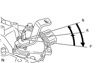
Turn the lever clockwise until it stops, and then turn it counterclockwise 2 notches.
Remove the control shaft lever.
-
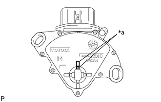
*a
Protrusion
Align the protrusions of the park/neutral position switch assembly as shown in the illustration.
Hold the switch in that position and tighten the 2 bolts.
5.4 N*m
55 kgf*cm
48 in.*lbf
Note:After installing the park/neutral position switch assembly, confirm that the 2 protrusions on the park/neutral position switch assembly are aligned.
-
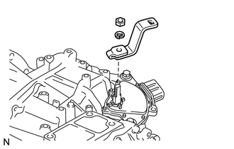
Install the control shaft lever to the control shaft with the washer and nut.
12.7 N*m
130 kgf*cm
9 ft.*lbf
-
INSTALL TRANSMISSION BREATHER HOSE SUB-ASSEMBLY
-
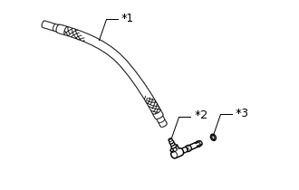
*1
Breather Plug Hose
*2
Breather Plug
*3
O-ring
Coat a new O-ring with ATF and install it to the breather plug.
Install the breather plug to the breather plug hose.
-
Install the transmission breather hose sub-assembly to the transaxle case.
-