ENTRY AND START SYSTEM(for Entry Function) SYSTEM DESCRIPTION
SYSTEM DESCRIPTION
The following pattern will be used: "Operation" indicates user operation using the entry and start system. "Expected operation of the vehicle" indicates how a known good vehicle will react in accordance with each operation. "Suspected Area/Diagnosis" indicates suspected malfunctioning areas and tips for each diagnosis if the vehicle did not react as expected.
Example: Operation No.
Operation
-
Expected operation of the vehicle
-
Waveform or Output Value
-
Suspected Area
Diagnosis
-
-
BASIC PRECAUTIONS
Entry and start system (for Entry Function) data and Diagnostic Trouble Codes (DTCs) can be checked using the GTS.
Check for DTCs using the following procedure. If any DTCs are output, diagnose those DTCs first.
Connect the GTS to the DLC3.
Turn the engine switch on (IG).
Enter the following menus: Body Electrical / Entry&Start, Power Source Control or Starting Control / Trouble Codes.
When using the GTS with the engine switch off, connect the GTS to the DLC3 and turn a courtesy light switch on and off at intervals of 1.5 seconds or less until communication between the GTS and the vehicle begins. Then select Model Code "KEY REGIST" under manual mode and enter the following menus: Body Electrical / Entry&Start(CAN). While using the GTS, periodically turn a courtesy light switch on and off at intervals of 1.5 seconds or less to maintain communication between the GTS and the vehicle.
If the entry and start system customize setting "Auto Entry Cancel SW" is ON or the system has been canceled by manual operation, cancel the entry and start system cancel function before troubleshooting the entry and start system (for Entry Function).
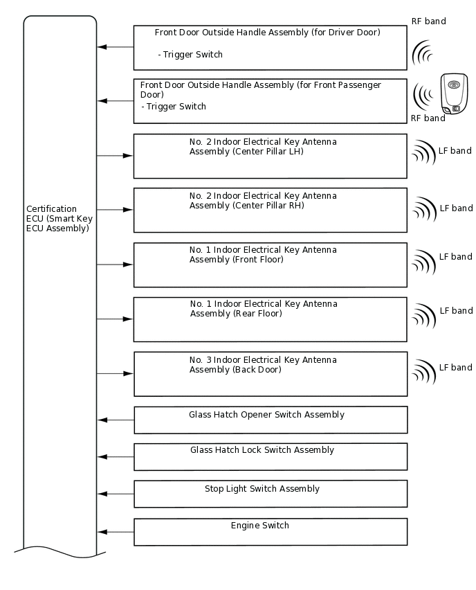
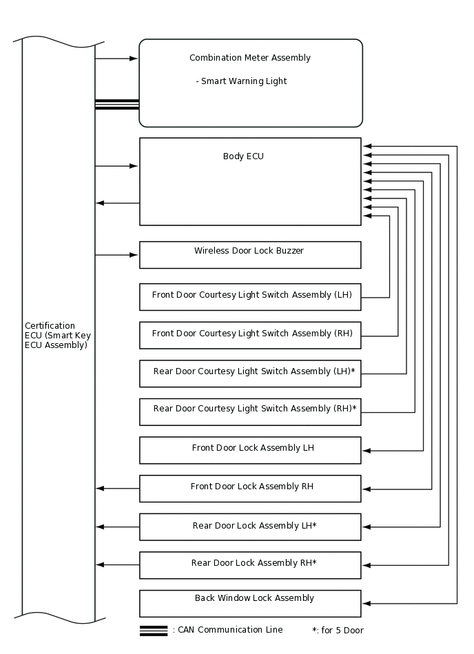
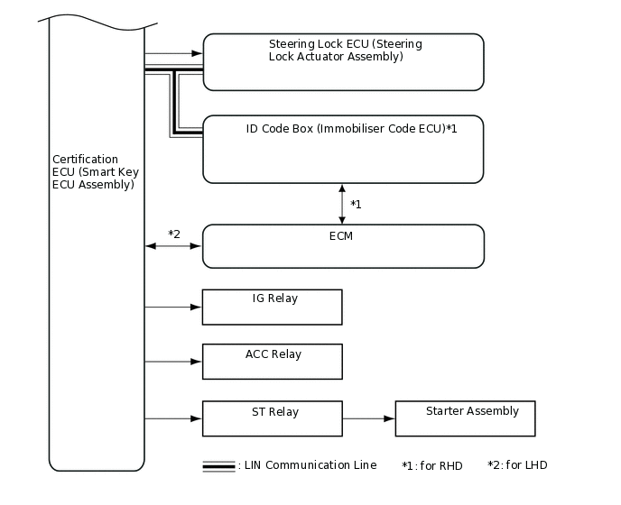
DIAGRAM OF ENTRY AND START SYSTEM
MULTI CHANNEL FUNCTION
The electrical key transmitter sub-assembly and certification ECU (smart key ECU assembly) can operate on two different RF channels. When an electrical key transmitter sub-assembly is brought within an exterior detection area, key verification begins. If key verification fails due to wave interference, the channel will be switched and key verification will be performed again.
The multi channel system begins verification using the channel on which the last verification was successfully performed. If the verification fails, the system switches to the other channel.
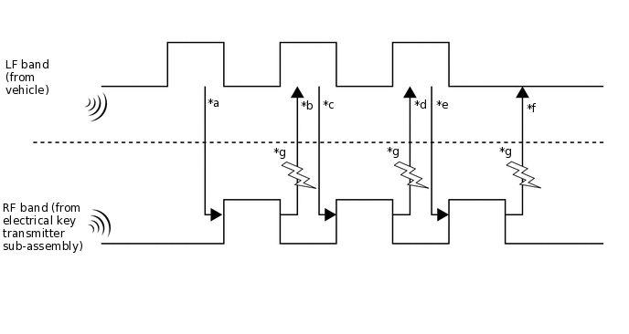
*a
Exterior detection areas are created using LF waves to receive a response from the electrical key transmitter sub-assembly.
*b
When the electrical key transmitter sub-assembly is brought into an exterior detection area, it receives LF waves from the vehicle. Using RF waves, the electrical key transmitter sub-assembly responds to the vehicle.
*c
Upon receiving the response from the electrical key transmitter sub-assembly, the certification ECU (smart key ECU assembly) activates the electrical key antennas (outside) one by one. Using LF waves, the certification ECU (smart key ECU assembly) determines which exterior detection area the electrical key transmitter sub-assembly is in.
*d
The electrical key transmitter sub-assembly receives the LF waves from the vehicle and responds using RF waves. (The certification ECU (smart key ECU assembly) recognizes which exterior detection area the electrical key transmitter sub-assembly is in.)
*e
The certification ECU (smart key ECU assembly) sends registered key ID information to the electrical key transmitter sub-assembly using LF waves. (Up to 4 key IDs can be registered.)
*f
The electrical key transmitter sub-assembly sends the key ID information using RF waves. When the certification ECU (smart key ECU assembly) receives it, verification completes.
*g
Wave interference (Channel switching)
-
-
The multi channel system changes the channel when the RF band (*b, *d and *f) is interrupted by wave interference. Refer to the table below to confirm when the system changes the channel.
*b or *d is NG
*f is NG
Condition
RF waves cannot be received
RF waves cannot be received properly
RF waves cannot be received
RF waves cannot be received properly
Channel switching
The channel will not be switched.
The channel will be switched.
The channel will not be switched.
The channel will be switched*.
*: The channel is not switched during vehicle interior verification after an entry lock operation is performed.
DIAGNOSIS IN ACCORDANCE WITH USER OPERATION
Operation 1
Operation
Turn the engine switch off and lock all the doors, then take the electrical key transmitter sub-assembly approximately 3 m (9.84 ft.) or more away from the vehicle.
Operation 2
Operation
While carrying the electrical key transmitter sub-assembly, press the trigger switch on the front door outside handle assembly.
Tip:When the trigger switch is pressed, a request signal is sent from the indoor electrical key antenna, and an approximately 0.7 m (2.30 ft.) detection area is formed to detect the electrical key transmitter sub-assembly.
Signal transmission: Certification ECU (smart key ECU assembly) → No. 2 indoor electrical key antenna assembly (center pillar LH) and No. 2 indoor electrical key antenna assembly (center pillar RH) → Electrical key transmitter sub-assembly → Certification ECU (smart key ECU assembly) → Body ECU
Expected operation of the vehicle
While the doors are unlocked, the answer-back is performed at the same time. If the answer-back is not performed at the same time any of the parts listed in the table below may be malfunctioning.
Waveform or Output Value
Pulse generation (E50-31 (CLG1) - E49-10 (E)*)
Pulse generation (E49-4 (TSW1) - E49-10 (E)*)
Suspected Area
Diagnosis
Electrical key transmitter sub-assembly
The key ID code sent by the electrical key transmitter sub-assembly does not match the key ID code stored in the certification ECU (smart key ECU assembly). Use another electrical key transmitter sub-assembly to check the operation.
Press the lock and unlock buttons of the electrical key transmitter sub-assembly to check the operation. If the doors can be locked and unlocked, that means the detection area has not been formed. Parts other than the electrical key transmitter sub-assemblies and "Certification ECU (smart key ECU assembly)" may be malfunctioning.
If the electrical key transmitter sub-assembly is malfunctioning, the engine cannot be started and the engine switch cannot be turned on (ACC) or on (IG). Under normal conditions, the smart warning light in the combination meter assembly blinks (green) slowly when the engine switch is pressed with the electrical key transmitter sub-assembly in the driver seat area, the shift lever in N*1 and the brake pedal*1 or clutch pedal released*2.
Tip:If the door cannot be unlocked, use the mechanical key built into in the electrical key transmitter sub-assembly to unlock the door.
Before replacing the electrical key transmitter sub-assembly, check if the transmitter battery is depleted.
Transmitter battery is depleted
Press and hold the lock switch of the electrical key transmitter sub-assembly for 5 seconds and check the number of times that the transmitter LED blinks. If the transmitter LED does not blink or blinks only once or twice, the transmitter battery may be depleted. If the transmitter LED does not blink at all, the electrical key transmitter sub-assembly may be malfunctioning.
If the transmitter battery voltage at the time the electrical key transmitter sub-assembly sends a signal drops to 2.2 V or less, Yes is displayed for the Data List item Key Low Battery.
If the transmitter battery voltage drops to 2.0 V or lower, operation cannot be assured.
Tip:The output of the electrical key transmitter sub-assembly will decrease if it is in low temperatures.
When the transmitter battery is depleted, the engine cannot be started and the engine switch cannot be turned on (ACC) or on (IG) normally. If the electrical key transmitter sub-assembly is held near the engine switch, the engine can be started.
Make sure that the transmitter battery type and installation direction are correct.
Wave Interference
If the problem occurs in certain locations or times of day, the possibility of wave interference is high.
If the electrical key transmitter sub-assembly is malfunctioning, the transmitter battery is depleted, an electrical key transmitter sub-assembly from another vehicle has been used or wave interference is suspected, "Yes" may be displayed for any of the following Data List items: "Unmatch Code or Form", "No Response", "ID Code Difference" or "Unmatched Vehicle-ID"
Certification ECU (smart key ECU assembly)
If the certification ECU (smart key ECU assembly) is malfunctioning, it is not possible to unlock the front passenger door.
If the certification ECU (smart key ECU assembly) is malfunctioning, wireless unlock cannot be performed.
If the certification ECU (smart key ECU assembly) is malfunctioning, the engine switch cannot be turned on (ACC) and the engine cannot be started (excluding emergency operation).
Formation of the vehicle exterior detection area can be confirmed by using the GTS.
No. 2 indoor electrical key antenna assembly (center pillar LH)
No. 2 indoor electrical key antenna assembly (center pillar RH)
Vehicle exterior detection area is not formed properly.
Even if the vehicle exterior detection area is not formed properly, the engine switch can be turned on (ACC) and the engine can be started.
Formation of the vehicle exterior detection area can be confirmed by using the GTS.
Under normal conditions, "ON" is displayed for the Data List item "D-Door Trigger Switch" when the trigger switch is pressed.
Front door outside handle assembly (for driver door)
If the doors can be unlocked by pressing the trigger switch of the front passenger door while carrying the electrical key transmitter sub-assembly, the trigger switch of the driver door may be malfunctioning.
Vehicle Battery is discharged
It may be possible to tell whether the vehicle battery is discharged by operating the horn.
Door lock/unlock mechanism
If a door cannot be locked/unlocked by operating the door control switch on the door in the cabin, the door lock mechanism is malfunctioning.
Others
If the entry and start system function has been canceled through the customize function, the detection area will not be formed and the door lock function will not operate even if the trigger switch is pressed.
If the electrical key transmitter sub-assembly is in transmitter battery saving mode, even if it receives LF waves from the vehicle, it does not respond using RF waves, therefore the electrical key transmitter sub-assembly LED does not blink.
*1: for Multi-Mode Manual Transaxle
*2: for Manual Transaxle
Operation 3
Operation
After getting into the vehicle while carrying the electrical key transmitter sub-assembly, close the door and press the engine switch once with the shift lever in N*1 while not depressing the brake pedal*1 or clutch pedal*2.
Expected operation of the vehicle
The smart warning light in the combination meter assembly blinks (green) slowly, and the engine switch is turned on (ACC).
The steering is unlocked.
If any of the above operations are not performed, check the suspected areas in the following table.
Tip:When the engine switch is pressed, the indoor electrical key antenna forms a key detection area inside the vehicle and detects the electrical key transmitter sub-assembly in the cabin. The electrical key transmitter sub-assembly sends a key ID code upon receiving a request signal and the electrical key transmitter sub-assembly LED illuminates for a short time. After pressing the engine switch, if the key ID code sent by the electrical key transmitter sub-assembly matches the key ID code stored by the certification ECU (smart key ECU assembly), the ACC relay turns on and the smart warning light in the combination meter assembly blinks (green) slowly. After the power source mode has changed and L code verification has been completed, the steering will be unlocked and the immobiliser will be inactive. The Data List status of "Immobiliser" will then be changed from "Set" to "Unset".
Signal transmission: Certification ECU (smart key ECU assembly) → Indoor electrical key antenna assembly → Electrical key transmitter sub-assembly → Certification ECU (smart key ECU assembly)
Tip:The interior detection area is formed when any of the following conditions are met:
Any door is opened.
Within approximately 30 seconds after any of the doors have been opened and closed.
Within approximately 30 seconds after the brake*1 or clutch pedal*2 has been depressed.
Right after the engine switch is pressed.
Waveform or Output Value
Pulse generation (E50-31 (CLG1) - E49-10 (E)*3)
Pulse generation (E50-6 (CLG2) - E49-10 (E)*3)
Pulse generation (E50-9 (CLG5) - E49-10 (E)*3)
Pulse generation (E50-27 (CG6B) - E49-10 (E)*3)
*1: for Multi-Mode Manual Transaxle
*2: for Manual Transaxle
*3:Click here
Suspected Area
Diagnosis
Certification ECU (smart key ECU assembly)
-
Wave Interference
If malfunctions occur at a specific location/time, wave interference may be the cause.
If wave interference is suspected in the cabin, disconnect all the connectors of any additional devices which are not standard equipment, or remove the additional devices and check for noise.
Indoor electrical key antenna assemblies that form the interior detection areas.
If the interior detection areas are not formed properly, the engine cannot be started and the engine switch cannot be turned on (ACC) or on (IG). If the electrical key transmitter sub-assembly is held near the engine switch in an emergency, the engine can be started.
Using the GTS, enter key diagnostic mode to forcibly form the interior detection area. If the electrical key transmitter sub-assembly is brought into the interior detection area, short beeps will sound.
Engine switch
Under normal conditions, after the engine switch is pressed, "ON" is displayed for the Data List items "Start Switch1" and "Start Switch2".
ID code box (immobiliser code ECU)*1
In order to unlock the steering, it is necessary for "S Code Check" in the Data List to display "OK". If "S Code Check" displays "OK", the certification ECU (smart key ECU assembly) code and ID code box (immobiliser code ECU) code match.
Neutral start switch*3
Under normal conditions, "Neutral SW/ Clutch SW" in the Data List displays "ON" when the shift lever is moved to N.
Steering lock ECU (steering lock actuator assembly)
If "OK" is displayed for the Data List item "L Code Check" when the engine switch is turned on (ACC), power will be supplied to the steering motor for approximately 10 seconds. Then the ECU sends an unlock signal to the steering motor and the Data List item "Unlock Request Receive" temporarily changes from "NG" to "OK". After the steering unlocks, the ECU receives the unlock confirmation signal from the steering motor and the Data List item "Steering Unlock" changes from "Unset" to "Set".
In order to unlock the steering, it is necessary that "OK" is displayed for the Data List item "L Code Check" (the ID code stored in the steering lock ECU (steering lock actuator assembly) matches that of the ID code box (immobiliser code ECU)*1 or Certification ECU (smart key ECU assembly)*2)
*1: for RHD
*2: for LHD
*3: for Multi-Mode Manual Transaxle
Tip:The electrical key transmitter sub-assembly, the transmitter battery and the vehicle battery should have already been inspected in the previous operation steps. However, if they have not been inspected, inspect them.
Operation 4
Operation
Depress the clutch pedal*1 or brake pedal*2 with the shift lever in N*2 while carrying an electrical key transmitter sub-assembly.
Expected operation of the vehicle
The smart warning light in the combination meter assembly blinks (green). If it does not, check the suspected areas in the following table.
Suspected Area
Diagnosis
Stop light switch assembly*1
If the brake pedal is depressed, "ON" is displayed for the Data List item "Stop Light Switch1".
Clutch start switch assembly*2
If the clutch pedal is depressed, "ON" is displayed for the Data List item "Neutral SW/ Clutch SW".
Certification ECU (smart key ECU assembly)
Entry and Start System (for Start Function)-Terminals of ECU
*1: for Manual Transaxle
*2: for Multi-Mode Manual Transaxle
Operation 5
Operation
After getting into the vehicle while carrying the electrical key transmitter sub-assembly, press the engine switch with the shift lever in N*1 while depressing the brake pedal*1 or clutch pedal*2.
Expected operation of the vehicle
The engine starts. If it does not, check the suspected areas in the following table.
Suspected Area
Diagnosis
Steering lock system
Under normal conditions, the steering is unlocked and "ON" is displayed for the Data List item "Steering Unlock Switch".
Vehicle Battery is discharged
Whether the vehicle battery is discharged or not can be checked easily by operating the horn.
*1: for Multi-Mode Manual Transaxle
*2: for Manual Transaxle
Operation 6
Operation
Press the engine switch.
Expected operation of the vehicle
The engine stops, the smart warning light illuminates and then goes off.
Operation 7
Operation
Open any of the doors with the engine switch off.
Expected operation of the vehicle
The steering locks. If it does not, check the suspected areas in the following table.
Suspected Area
Diagnosis
Steering lock system
-
Door courtesy light switch assembly
When the front door LH is opened, "ON" is displayed for the Data List item "FL Door Courtesy SW".*1
When the front door RH is opened, "ON" is displayed for the Data List item "FR Door Courtesy SW".*2
*1: for LHD
*2: for RHD
Operation 8
Operation
While carrying the electrical key transmitter sub-assembly, press the trigger switch on the front door outside handle assembly (for driver door).
Expected operation of the vehicle
Answer-back is performed at the same time when the doors are locked.
WIRELESS DOOR LOCK BUZZER VOLUME ADJUSTMENT FUNCTION
The volume of the wireless door lock buzzer can be changed through the customize function.
Tip:The volume of the following wireless door lock buzzer operations cannot be adjusted.
Warning function buzzer operations
Customize function buzzer operations
Buzzer operations for key diagnostic mode using the GTS
Key registration buzzer operations
WARNING FUNCTION
Warning
When any of the following situations occur, the entry and start system causes the certification ECU (smart key ECU assembly) to sound the wireless door lock buzzer and a buzzer in the combination meter assembly, and the smart warning light in the combination meter assembly to illuminate in order to alert the driver.
Situation: The key reminder sounds.
When the driver door is open, the driver turns the engine switch on (ACC) and attempts to leave the vehicle.
Possible effects without warning
Vehicle theft
Warning Start Condition
(All conditions are met)
Condition 1
The engine switch is on (ACC).
The driver door is opened.
Condition 2 (Approval for one second or more)
The engine switch is off.
The steering is unlocked.
The driver door is opened.
Warning description
The buzzer in the combination meter assembly sounds continuously at short and even intervals.
Warning Stop Condition
(One condition is met)
The engine switch is turned on (IG).
The driver door is closed.
The engine switch is turned off and the steering is locked.
Situation: The engine is left running when the driver gets out of the vehicle.
There are 2 patterns for this situation.
-
Pattern 1:
When the engine is left running, the driver closes the driver door and attempts to leave the vehicle while carrying the electrical key transmitter sub-assembly.
In this situation, the following control is performed:
Possible effects without warning
Vehicle theft
Warning Start Condition
(All conditions are met)
The engine switch is on (ACC) or on (IG).
The driver door is opened → closed.
The electrical key transmitter sub-assembly is not in the vehicle.
No vehicle speed is detected.
Warning description
The buzzer in the combination meter assembly sounds once.
The wireless buzzer sounds 3 times.
The smart warning light flashes (orange) in the combination meter assembly.
Warning Stop Condition
(Either condition is met)
The engine switch is turned off.
The electrical key transmitter sub-assembly is returned to the vehicle.
-
Pattern 2:
In the same situation as pattern 1, the driver presses the trigger switch on the front door outside handle assembly.
In this situation, the following control is performed:
Possible effects without warning
Vehicle theft
Warning Start Condition
(All conditions are met)
The engine switch is on (ACC) or on (IG).
The electrical key transmitter sub-assembly is not in the inside detection areas.
The electrical key transmitter sub-assembly is in the outside detection areas.
The trigger switch on the front door outside handle assembly is pressed.
No vehicle speed is detected.
Warning description
The buzzer in the combination meter assembly sounds once.
The wireless buzzer sounds continuously.
The smart warning light flashes (orange) in the combination meter assembly.
Warning Stop Condition
(One condition is met)
The engine switch is turned off.
The vehicle speed is 5 km/h (3.11 mph) or more.
5 seconds have elapsed after the wireless door lock buzzer is activated (only wireless buzzer stops).
Any door is opened or closed (only wireless buzzer stops).
The electrical key transmitter sub-assembly is returned to the vehicle.
Situation: The engine is left running when a passenger gets out of the vehicle while carrying the electrical key transmitter sub-assembly.
When the engine is left running, a passenger leaves the vehicle while carrying the electrical key transmitter sub-assembly.
In this situation, the following control is performed:
Possible effects without warning
Engine cannot be restarted
Warning Start Condition
(All conditions are met)
The engine switch is on (ACC) or on (IG).
A door other than the driver door is opened → closed.
The electrical key transmitter sub-assembly is not in the vehicle.
No vehicle speed is detected.
Warning description
The buzzer in the combination meter assembly sounds once.
The wireless buzzer sounds 3 times.
The smart warning light flashes (orange) in the combination meter assembly.
Warning Stop Condition
(Either condition is met)
The engine switch is turned off.
The electrical key transmitter sub-assembly is returned to the vehicle.
Situation: The electrical key transmitter sub-assembly is not in the interior detection areas.
When the electrical key transmitter sub-assembly is not in the vehicle or the transmitter battery is depleted, the driver attempts to start the engine or turn the engine switch on (IG).
In this situation, the following control is performed:
Possible effects without warning
Confuses the user
Warning Start Condition
(All conditions are met)
A door is not unlocked using the mechanical key and the engine switch is pressed.
The electrical key transmitter sub-assembly is not in the vehicle or the transmitter battery is depleted.
The immobiliser system is set.
Warning description
The buzzer in the combination meter assembly sounds once.
The smart warning light flashes (orange) in the combination meter assembly.
Warning Stop Condition
(Either condition is met)
15 seconds elapse after warning starts.
The electrical key transmitter sub-assembly is returned to the vehicle.
30 seconds have elapsed after the door is opened.
Situation: The vehicle is driven without an electrical key transmitter sub-assembly.
When the vehicle starts moving without the registered electrical key transmitter sub-assembly in the vehicle.
In this situation, the following control is performed:
Possible effects without warning
Engine cannot be restarted
Warning Start Condition
(All conditions are met)
The engine switch is on (IG).
Warning for when a passenger gets out of the vehicle while carrying the electrical key transmitter sub-assembly is operating.
The vehicle speed is 5 km/h (3.11 mph) or more.
The electrical key transmitter sub-assembly is not in the vehicle.
Warning description
The buzzer in the combination meter assembly sounds nine times.
The smart warning light flashes (orange) in the combination meter assembly.
Warning Stop Condition
(Either condition is met)
The engine switch is turned off.
The electrical key transmitter sub-assembly is returned to the vehicle.
Situation: The electrical key transmitter sub-assembly is left in the vehicle.
The trigger switch on the front door outside handle assembly is pressed to perform operate the entry lock function with the electrical key transmitter sub-assembly left in the vehicle.
In this situation, the following control is performed:
Possible effects without warning
Vehicle theft
Warning Start Condition
(All conditions are met)
The engine switch is off.
All doors are closed.
The electrical key transmitter sub-assembly is in the vehicle.
The trigger switch on the front door outside handle assembly is on (pressed).
Any door is unlocked.
No vehicle speed is detected.
Warning description
The wireless buzzer sounds continuously for 5 seconds.
Warning Stop Condition
(One condition is met)
The engine switch is turned to a mode other than off.
The vehicle speed is 5 km/h (3.11 mph) or more.
A lock operation is detected.
Any door is opened.
Situation: Door is ajar.
The trigger switch on the front door outside handle assembly is pressed to operate the entry lock function with a door open.
In this situation, the following control is performed:
Possible effects without warning
Vehicle theft
Warning Start Condition
(All conditions are met)
The engine switch is off.
Any door is opened.
The trigger switch on or lock switch is pressed on the electrical key transmitter sub-assembly.
The electrical key transmitter sub-assembly is in an outside detection area.
Warning description
The wireless buzzer sounds continuously for 5 seconds.
Warning Stop Condition
(One condition is met)
The engine switch is turned to a mode other than off.
All doors are closed.
An unlock operation is performed using the wireless door lock remote function.
The trigger switch on the front door outside handle assembly is used to perform entry unlock.
Situation: The electrical key transmitter sub-assembly is locked inside the vehicle.
With a door open and the electrical key transmitter sub-assembly in the vehicle, the lock knob is locked and then the door is closed with the door handle being pulled.
In this situation, the following control is performed:
Possible effects without warning
Vehicle theft
Warning Start Condition
(All conditions are met)
Condition 1
With a door open, the lock knob is locked and then the door is closed with the door handle being pulled.
The electrical key transmitter sub-assembly is in the vehicle.
No vehicle speed is detected.
Condition2*
The engine switch is off.
All doors are closed and locked.
Lock operation other than entry lock operation is performed.
Electrical key transmitter sub-assembly is inside vehicle (matching code is detected in vehicle interior).
Warning description
The buzzer in the combination meter assembly sounds once.
The wireless buzzer sounds continuously for 5 seconds.
Warning Stop Condition
(One condition is met)
The engine switch is turned to a mode other than off.
Any door is opened.
A lock operation is detected.
The vehicle speed is 5 km/h (3.11 mph) or more.
*: for RHD
Situation: The transmitter battery is weak.
The vehicle is driven using an electrical key transmitter sub-assembly that has a low transmitter battery.
In this situation, the following control is performed:
Possible effects without warning
Depleted transmitter battery, engine cannot be restarted
Warning Start Condition
(All conditions are met)
Condition 1
The engine switch is turned off after being left on (IG) for more than 20 minutes.
The transmitter battery voltage is low.
The electrical key transmitter sub-assembly is in the vehicle.
No vehicle speed is detected.
Condition 2
The engine is off → the engine is started.
The transmitter battery voltage is low.
The electrical key transmitter sub-assembly is in the vehicle.
No vehicle speed is detected.
Condition 1 is met. (past)
Warning description
The buzzer in the combination meter assembly sounds once.
The smart warning light flashes (orange) in the combination meter assembly for 15 seconds.
Warning Stop Condition
(Either condition is met)
The vehicle speed is 5 km/h (3.11 mph) or more.
The transmitter battery is replaced with a new one.
Situation: The steering cannot be released.
The steering cannot be released, thus the engine is prevented from starting.
In this situation, the following control is performed:
Possible effects without warning
User does not notice that the steering is locked
Warning Start Condition
The steering cannot be unlocked.
Warning description
The buzzer in the combination meter assembly sounds once.
The smart warning light flashes (green) in the combination meter assembly.
Warning Stop Condition
The steering is unlocked.
Situation: The entry and start system is malfunctioning.
When an IG circuit malfunction, vehicle speed signal malfunction or malfunction that interferes with steering lock ECU (steering lock actuator assembly) operation is detected.
In this situation, the following control is performed:
Possible effects without warning
Malfunction cannot be detected
Warning Start Condition
(One condition is met)
The steering lock ECU (steering lock actuator assembly), driver of the certification ECU (smart key ECU assembly) or unlock detection switch is malfunctioning.
An IG relay output circuit malfunction occurs three times or more consecutively.
The vehicle speed is judged as abnormal or vehicle speed signal communication is malfunctioning.
Warning description
The buzzer in the combination meter assembly sounds once.
The smart warning light flashes (orange) in the combination meter assembly for 15 seconds.
Warning Stop Condition
The system returns to normal.
Situation: The engine does not start.
When the engine switch is pressed, the electrical key transmitter sub-assembly cannot be detected in the vehicle two times in a row.
In this situation, the following control is performed:
Possible effects without warning
Engine cannot be restarted
Warning Start Condition
(One condition is met)
The immobiliser system is set.
The electrical key transmitter sub-assembly is not in the vehicle.
A key code verification error occurs when the engine switch is pressed twice or the driver door key linked unlock operation is performed.
Warning description
The buzzer in the combination meter assembly sounds once.
The smart warning light flashes (orange) in the combination meter assembly for 60 seconds.
Warning Stop Condition
(Either condition is met)
The electrical key transmitter sub-assembly is in the vehicle.
30 seconds have elapsed after the door is opened
Situation: Immobiliser system certification completion occurs.
When an electrical key transmitter sub-assembly with a depleted transmitter battery is held near to the engine switch while depressing the *1 or clutch pedal*2.
In this situation, the following control is performed:
Possible effects without warning
Malfunction cannot be detected
Warning Start Condition
The electrical key transmitter sub-assembly certification result is OK.
Warning description
The buzzer in the combination meter assembly sounds once.
*1: for Multi-Mode Manual Transaxle
*2: for Manual Transaxle
Situation: Warning buzzer sounds when engine switch operated while driving.
When the engine switch is pressed while the vehicle is being driven.
In this situation, the following control is performed:
Possible effects without warning
Engine accidentally stopped
Warning Start Condition (All conditions are met)
The engine is running at 200 rpm or more.
The vehicle speed is 5 km/h (3.11 mph) or more.
The engine switch is pressed.
Warning description
The buzzer in the combination meter assembly sounds continuously at short and even intervals.
Warning Stop Condition (Either condition is met)
1.8 seconds have elapsed after operation of the engine switch is stopped.
The engine switch is turned off.