CYLINDER HEAD INSPECTION
PROCEDURE
INSPECT CYLINDER HEAD SUB-ASSEMBLY
Using a precision straightedge and feeler gauge, measure the warpage of the contact surfaces where the cylinder head sub-assembly contacts the cylinder block sub-assembly and each manifold.
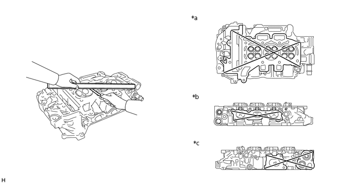
*a
Bottom Side
*b
Intake Manifold Side
*c
Exhaust Manifold Side
-
-
Maximum Warpage
Item
Specified Condition
Bottom side
0.05 mm (0.00197 in.)
Intake manifold side
0.05 mm (0.00197 in.)
Exhaust manifold side
0.05 mm (0.00197 in.)
If the warpage is more than the maximum, replace the cylinder head sub-assembly.
-
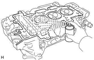
Using a dye penetrant, check the intake ports, exhaust ports and cylinder head sub-assembly surface for cracks.
If cracks are found, replace the cylinder head sub-assembly.
Measure the diameter of the camshaft bearing.
Standard Camshaft Bearing Diameter
24.0 to 24.1 mm (0.945 to 0.949 in.)
If the result is not as specified, replace the cylinder head sub-assembly.
INSPECT INNER COMPRESSION SPRING
Tip:The intake and exhaust valve springs are identical.
-
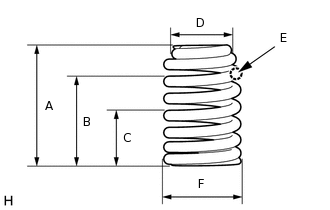
Inspect the inner compression spring.
Standard
Item
Specified Condition
A
Height not under load
47.2 mm (1.86 in.)
B
Height under load 1.75 N
31.5 mm (1.24 in.)
C
Height under load 2.87 N
23.0 mm (0.906 in.)
D
Spring diameter at the top
16.1 mm (0.634 in.)
E
Spring wire diameter
2.6 mm (0.102 in.)
F
Spring diameter at the base
20.9 mm (0.823 in.)
-
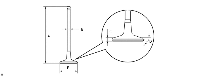
INSPECT INTAKE VALVE
Inspect the intake valve.
Standard
Item
Specified Condition
A
Length
92.57 mm (3.64 in.)
B
Diameter
4.970 to 4.985 mm (0.1957 to 0.1963 in.)
C
Height
2.92 mm (0.115 in.)
D
Angle
44°10' to 44°20'
E
Diameter
29.02 to 29.22 mm (1.143 to 1.150 in.)
INSPECT EXHAUST VALVE
Inspect the exhaust valve.
Standard
Item
Specified Condition
A
Length
91.85 mm (3.62 in.)
B
Diameter
4.9525 to 4.9675 mm (0.1950 to 0.1956 in.)
C
Height
2.97 mm (0.117 in.)
D
Angle
43°52' to 44°92'
E
Diameter
25.9 to 26.1 mm (1.020 to 1.028 in.)
INSPECT VALVE GUIDE BUSH
Inspect the valve guide bush.
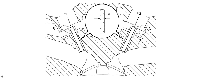
*1
Intake Valve Guide
*2
Exhaust Valve Guide
Standard
Item
Specified Condition
A
Diameter
5.000 to 5.015 mm (0.1969 to 0.1974 in.)
B
Height
8.6 to 10.0 mm (0.339 to 0.394 in.)
C
Height
8.1 to 9.5 mm (0.319 to 0.374 in.)
If the result is not as specified, replace the cylinder head sub-assembly.
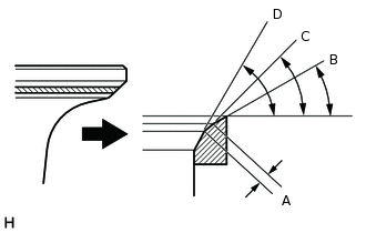
INSPECT INTAKE VALVE SEAT
Apply a light coat of Prussian blue to the valve face.
-
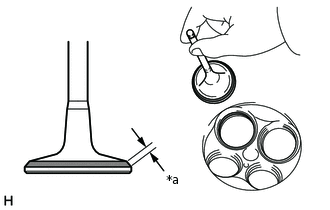
*a
Width
Lightly press the valve face against the intake valve seat.
Tip:Do not rotate the intake valve while pressing it.
Check the valve face and intake valve seat by using the following procedure:
If Prussian blue appears 360° around the entire valve face, the valve face is concentric. If not, replace the intake valve.
If Prussian blue appears 360° around the entire intake valve seat, the intake valve guide and valve face are concentric. If not, resurface the intake valve seat.
Check that the intake valve seat contacts the middle of the valve face with the width between 1.0 and 1.4 mm (0.0394 and 1.0551 in.).
-
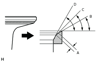
Inspect the intake valve seat.
Standard
Item
Specified Condition
A
Width
1.0 to 1.4 mm (0.0394 to 0.0551 in.)
B
Angle
30 degrees
C
Angle
45 degrees
D
Angle
60 degrees
If the result is not as specified, replace the cylinder head sub-assembly. If necessary, replace the intake valve.
INSPECT EXHAUST VALVE SEAT
Apply a light coat of Prussian blue to the valve face.
-
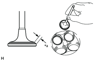
*a
Width
Lightly press the valve face against the exhaust valve seat.
Tip:Do not rotate the exhaust valve while pressing it.
Check the valve face and exhaust valve seat by using the following procedure:
If Prussian blue appears 360° around the entire exhaust valve face, the valve face is concentric. If not, replace the exhaust valve.
If Prussian blue appears 360° around the entire exhaust valve seat, the exhaust valve guide and valve face are concentric. If not, resurface the exhaust valve seat.
Check that the exhaust valve seat contacts the middle of the valve face with the width between 1.2 and 1.6 mm (0.0472 and 0.063 in.).
-
Inspect the exhaust valve seat.
Standard
Item
Specified Condition
A
Width
1.2 to 1.6 mm (0.0472 to 0.063 in.)
B
Angle
30 degrees
C
Angle
45 degrees
D
Angle
60 degrees
If the result is not as specified, replace the cylinder head sub-assembly. If necessary, replace the exhaust valve.
INSPECT CAMSHAFT THRUST CLEARANCE
Clean the camshaft bearing caps, cylinder head sub-assembly and camshaft journals.
Place the intake camshaft and exhaust camshaft on the cylinder head sub-assembly.
Install the camshaft bearing caps.
-
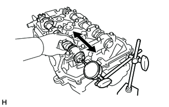
Using a dial indicator, measure the thrust clearance while moving the camshaft back and forth.
Minimum Thrust Clearance
Item
Specified Condition
Intake
0.1 mm (0.00394 in.)
Exhaust
0.1 mm (0.00394 in.)
Maximum Thrust Clearance
Item
Specified Condition
Intake
0.2 mm (0.00787 in.)
Exhaust
0.2 mm (0.00787 in.)
If the thrust clearance is more than the maximum, replace the cylinder head sub-assembly. If the thrust surface is damaged, replace the camshaft.