CAN COMMUNICATION SYSTEM
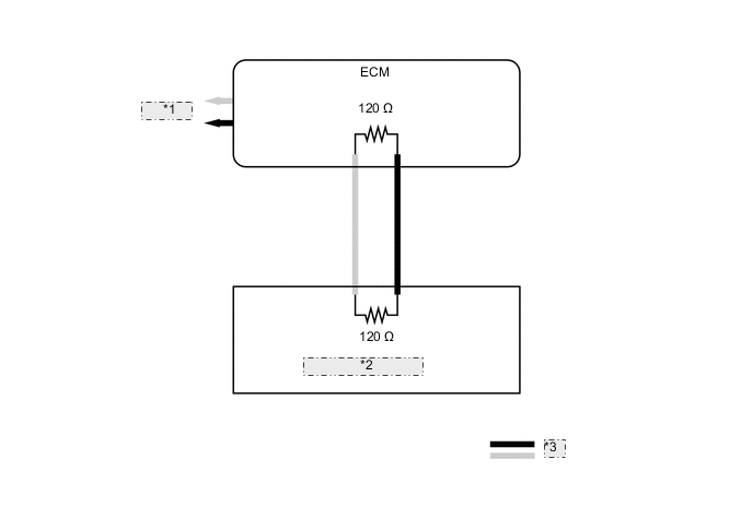
Figure 1. V Bus RHD (Models without Central Gateway ECU)
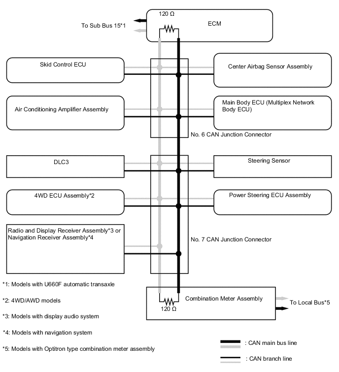
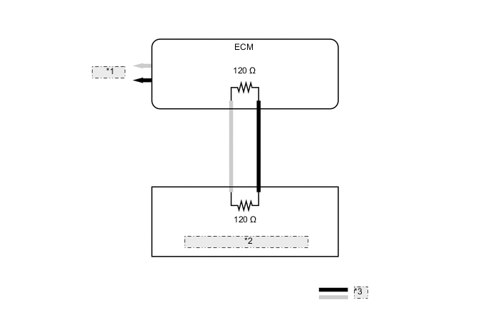
Figure 2. V Bus LHD (Models without Central Gateway ECU)
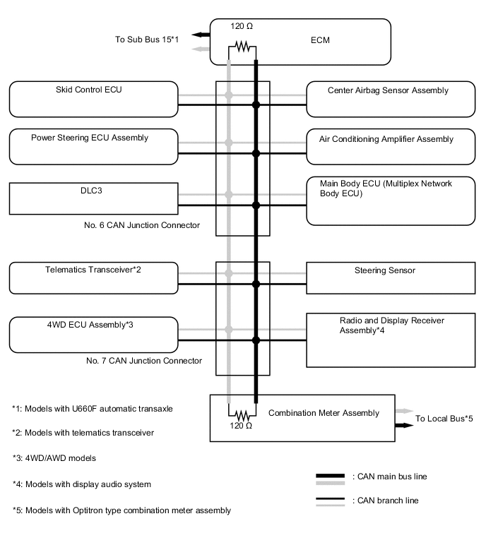
Figure 3. Bus 2 RHD (Models with Central Gateway ECU)
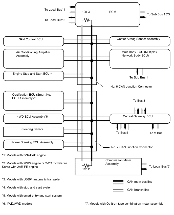
Figure 4. Bus 2 LHD (Models with Central Gateway ECU)
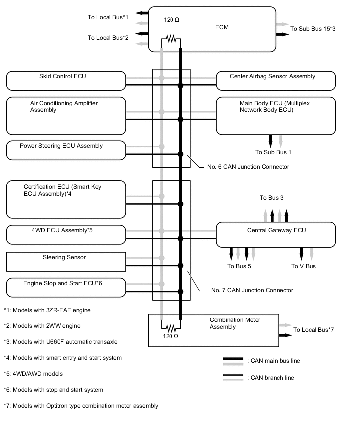
Figure 5. Bus 5 RHD/LHD (Models with Central Gateway ECU)
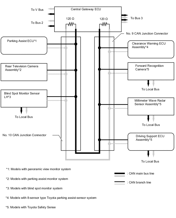
Figure 6. Bus 3 RHD (Models with Central Gateway ECU)
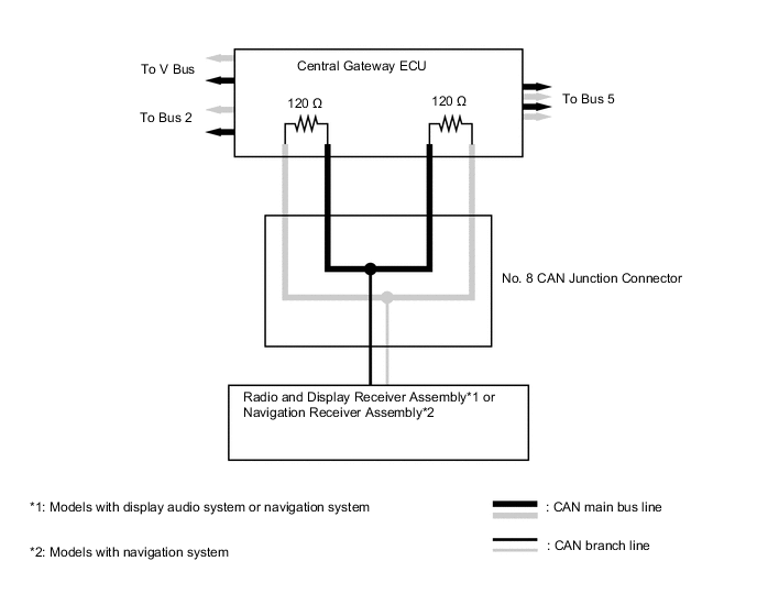
Figure 7. Bus 3 LHD (Models with Central Gateway ECU)
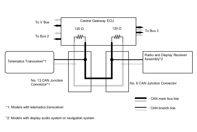
Figure 8. V Bus RHD/LHD (Models with Central Gateway ECU)
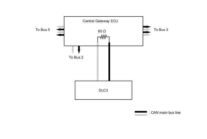
Figure 9. Sub Bus 1 RHD/LHD (Models with Central Gateway ECU)
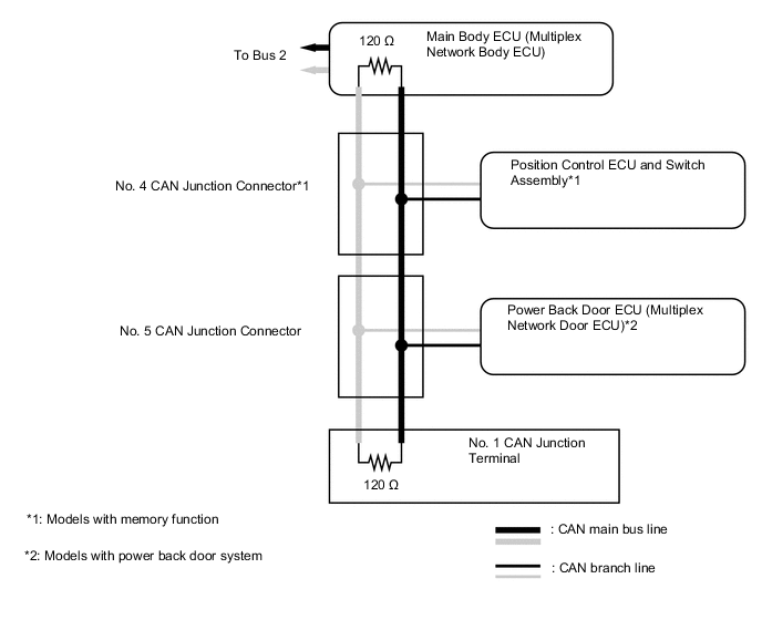
Figure 10. Local Bus (Models with Toyota Safety Sence)
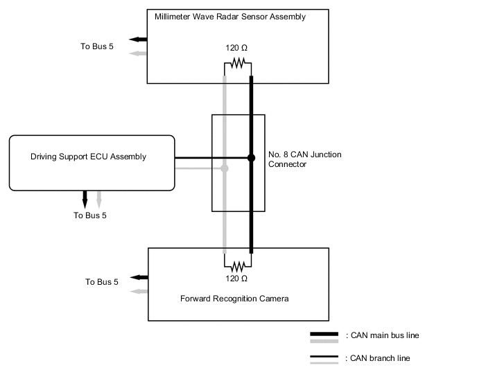
Figure 11. Sub Bus 15 (Models with U660F Automatic Transaxle)
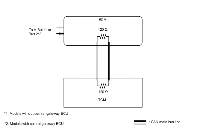
Figure 12. Local Bus (Models with Blind Spot Monitor System)
| *1 | Blind Spot Monitor Sensor LH |
| *2 | To Bus 5 |
| *3 | Blind Spot Monitor Sensor RH |
| *4 | CAN main bus line |
Figure 13. Local Bus (Models with 2WW Engine or 2WD Models for Korea with 2AR-FE Engine )
| *1 | To Bus 2 |
| *2 | Generator Control ECU Assembly |
| *3 | CAN main bus line |
Figure 14. Local Bus (Models with Optitron Type Combination Meter Assembly)
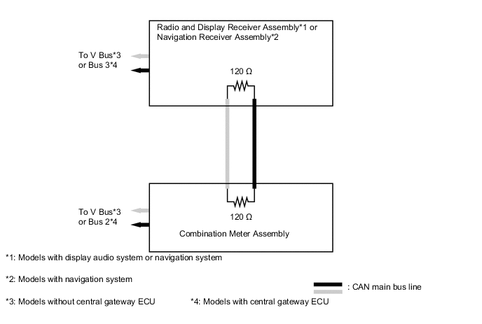
Figure 15. Local Bus (Models with 3ZR-FAE Engine)
| *1 | To Bus 2 |
| *2 | VALVEMATIC Actuator |
| *3 | CAN main bus line |