MANUAL TRANSAXLE UNIT REASSEMBLY
PROCEDURE
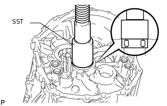
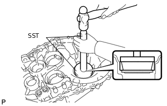
INSTALL SHIFT FORK SHAFT BEARING
-
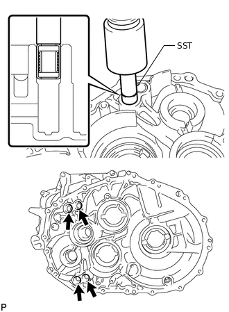
Using SST and a press, press in 4 new shift fork shaft bearings to the front transaxle case.
09820-00031
Clearance
0 to 0.5 mm (0.000 to 0.0197 in.)
-
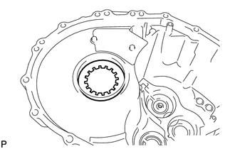
INSTALL OUTPUT SHAFT COVER
-
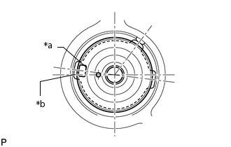
*a
Protrusion
*b
Groove
Align the protrusion on the output shaft cover with the groove on the front transaxle case, as shown in the illustration, and install the cover to the front transaxle case.
-
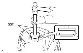
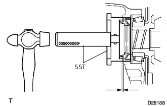
INSTALL NO. 2 OUTPUT SHAFT FRONT BEARING OUTER RACE
-
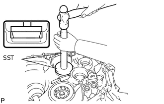
Using SST and a hammer, install the No. 2 output shaft front bearing to the front transaxle case.
09950-70010
09951-07100
09950-60020
09951-00710
-
INSTALL OUTPUT SHAFT COVER
-
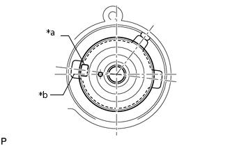
*a
Protrusion
*b
Groove
Align the protrusion on the output shaft cover with the groove on the front transaxle case, as shown in the illustration, and install the cover to the front transaxle case.
-
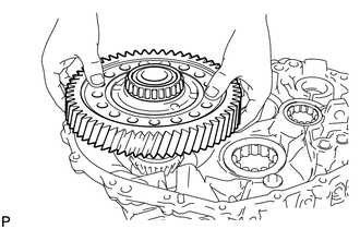
INSTALL OUTPUT SHAFT FRONT BEARING
-
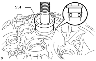
Coat a new output shaft front bearing with gear oil. Using SST and a press, install the output shaft front bearing.
09223-15020
-
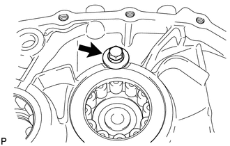
Install the bolt.
11.3 N*m
115 kgf*cm
8 ft.*lbf
-
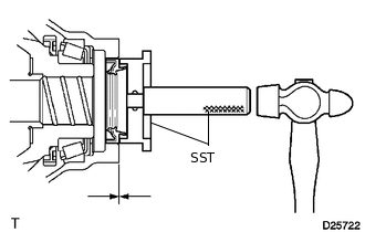
INSTALL FRONT TRANSAXLE CASE OIL SEAL
-
Using SST and a hammer, install a new front transaxle case oil seal to the front transaxle case.
09950-60010
09951-00580
09950-70010
09951-07200
Drive in Depth
4.4 to 5.0 mm (0.173 to 0.197 in.)
Coat a front transaxle case oil seal lip with MP grease.
-
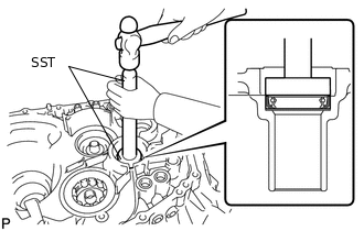
INSTALL INPUT SHAFT FRONT BEARING
-
Coat a new input shaft front bearing with gear oil. Using SST and a press, install the input shaft front bearing.
09223-00010
-
Install the bolt.
11.3 N*m
115 kgf*cm
8 ft.*lbf
-
INSTALL INPUT SHAFT REAR BEARING SHAFT SNAP RING
-
Using snap ring pliers, install the input shaft rear bearing shaft snap ring and output shaft rear bearing shaft snap ring to the manual transmission case.
-
INSTALL SHIFT AND SELECT LEVER SHAFT NEEDLE ROLLER BEARING
-
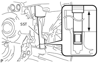
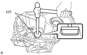
Using SST and a press, press in a new shift and select lever shaft needle roller bearing to the manual transmission case.
09285-76010
Clearance
177.8 to 178.7 mm (7.00 to 7.04 in.)
-
INSTALL SHIFT FORK SHAFT BEARING
-
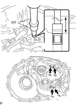
*a
Clearance A
*b
Clearance B
Using SST and a press, press in 4 new shift fork shaft bearings to the manual transmission case.
09307-12010
09820-00031
Clearance A
168.2 to 169.3 mm (6.62 to 6.67 in.)
Clearance B
162.2 to 163.3 mm (6.39 to 6.43 in.)
-
INSTALL FRONT DIFFERENTIAL CASE FRONT BEARING OUTER RACE
-
Using SST and a hammer, install the front differential case front bearing outer race to the front transaxle case.
09950-60020
09951-00910
09950-70010
09951-07150
-
INSTALL FRONT DIFFERENTIAL CASE REAR SHIM
-
Install the front differential case rear shim to the manual transmission case.
-
INSTALL FRONT DIFFERENTIAL CASE REAR BEARING OUTER RACE
-
Using SST and a hammer, install the front differential case rear bearing outer race to the manual transmission case.
09950-60020
09951-00910
09950-70010
09951-07100
-
ADJUST DIFFERENTIAL SIDE BEARING PRELOAD
-
Install differential gear assembly to the front transaxle case.
-
Install the manual transmission case to the manual transaxle case with the 12 bolts.
29.4 N*m
300 kgf*cm
22 ft.*lbf
-
Install the 6 bolts to the manual transaxle case side.
29.4 N*m
300 kgf*cm
22 ft.*lbf
Turn the differential case in both directions to settle it.
-
*a
Mark
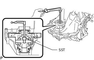
Using SST and a torque wrench, measure the starting preload.
09564-33010
Bearing Preload
1.00 to 2.49 N*m (10 to 25 kgf*cm, 9 to 22 in.*lbf)
Select a front differential case rear shim.
Table 1. Front Differential Case Rear Shim Thickness: Mark
Thickness mm (in.)
Mark
Thickness mm (in.)
Mark
Thickness mm (in.)
0
1.99 to 2.01
(0.0783 to 0.0791)
6
2.29 to 2.31
(0.0902 to 0.0909)
C
2.59 to 2.61
(0.1020 to 0.1028)
1
2.04 to 2.06
(0.0803 to 0.0811)
7
2.34 to 2.36
(0.0921 to 0.0929)
D
2.64 to 2.66
(0.1039 to 0.1047)
2
2.09 to 2.11
(0.0823 to 0.0831)
8
2.39 to 2.41
(0.0941 to 0.0949)
E
2.69 to 2.71
(0.1059 to 0.1067)
3
2.14 to 2.16
(0.0843 to 0.0850)
9
2.44 to 2.46
(0.0961 to 0.0969)
F
2.74 to 2.76
(0.1079 to 0.1087)
4
2.19 to 2.21
(0.0862 to 0.0870)
A
2.49 to 2.51
(0.0980 to 0.0988)
G
2.79 to 2.81
(0.1098 to 0.1106)
5
2.24 to 2.26
(0.0882 to 0.0890)
B
2.54 to 2.56
(0.1000 to 0.1008)
H
2.84 to 2.86
(0.1118 to 0.1126)
Remove the 6 bolts from the front transaxle case side.
Remove the 12 bolts from the manual transmission case side.
Remove the manual transmission case from the front transaxle case.
Remove the differential gear assembly from the front transaxle case.
-
INSTALL NO. 2 OUTPUT SHAFT REAR BEARING OUTER RACE
-
*a
Mark
Install the output shaft rear bearing shim to the manual transmission case.
Tip:When reusing the No. 2 output shaft rear bearing outer race, first install a output shaft rear bearing shim of the same thickness as the original. When installing a new No. 2 output shaft rear bearing outer race, first select and install a output shaft rear bearing shim which is thinner than the original.
-
Using SST and a hammer, install the No. 2 output shaft rear bearing outer race to the manual transmission case.
09950-60010
09951-00650
09950-70010
09951-07200
-
ADJUST NO. 2 OUTPUT SHAFT REAR BEARING PRELOAD
-
Install the No. 2 output shaft assembly and differential gear assembly to the front transaxle case.
-
Install the manual transmission case to the front transaxle case with the 12 bolts.
29.4 N*m
300 kgf*cm
22 ft.*lbf
-
Install the 6 bolts to the manual transaxle case side.
29.4 N*m
300 kgf*cm
22 ft.*lbf
-
Using SST, measure the No. 2 output shaft rear bearing preload. Subtract the value of the differential side bearing preload from the measured No. 2 output shaft rear bearing preload. Select a output shaft rear bearing shim that will set the preload within the specified range below and install the output shaft rear bearing shim.
09564-33010
Bearing Preload
3.66 to 5.18 N*m (37 to 53 kgf*cm, 32 to 46 in.*lbf)
Table 2. Output Shaft Rear Bearing Shim Thickness: Mark
Thickness mm (in.)
Mark
Thickness mm (in.)
Mark
Thickness mm (in.)
A
1.79 to 1.81
(0.0705 to 0.0713)
G
2.09 to 2.11
(0.0823 to 0.0831)
N
2.39 to 2.41
(0.0941 to 0.0949)
B
1.84 to 1.86
(0.0724 to 0.0732)
H
2.14 to 2.16
(0.0843 to 0.0850)
P
2.44 to 2.46
(0.0961 to 0.0969)
C
1.89 to 1.91
(0.0744 to 0.0752)
J
2.19 to 2.21
(0.0862 to 0.0870)
Q
2.49 to 2.51
(0.0980 to 0.0988)
D
1.94 to 1.96
(0.0764 to 0.0772)
K
2.24 to 2.26
(0.0882 to 0.0890)
R
2.54 to 2.56
(0.1000 to 0.1008)
E
1.99 to 2.01
(0.0783 to 0.0791)
L
2.29 to 2.31
(0.0902 to 0.0909)
S
2.59 to 2.61
(0.1020 to 0.1028)
F
2.04 to 2.06
(0.0803 to 0.0811)
M
2.34 to 2.36
(0.0921 to 0.0929)
T
2.64 to 2.66
(0.1039 to 0.1047)
Remove the 6 bolts from the front transaxle case side.
Remove the 12 bolts from the manual transmission case side.
Remove the manual transmission case from the front transaxle case.
Remove the No. 2 output shaft assembly from the front transaxle case.
Remove the differential gear assembly from the front transaxle case.
-
INSTALL TRANSMISSION MAGNET
-
Clean and reinstall the transmission magnet to the front transaxle case.
-
INSTALL DIFFERENTIAL GEAR ASSEMBLY
-
Coat the front differential case tapered roller bearings with gear oil and install it to the front transaxle case.
-
INSTALL TRANSMISSION OIL SEPARATOR
-
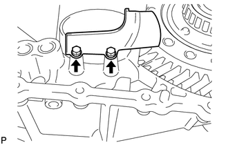
Install the transmission oil separator to the front transaxle case with the 2 bolts.
8.5 N*m
87 kgf*cm
75 in.*lbf
-
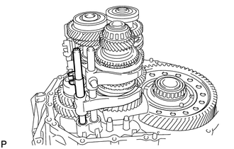
INSTALL INPUT SHAFT, NO. 1 OUTPUT SHAFT AND NO. 2 OUTPUT SHAFT
-
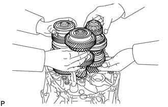
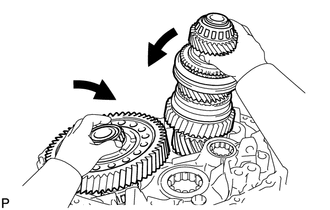
Install the 3 shafts at the same time.
-
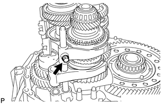
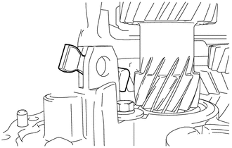
INSTALL REVERSE IDLER GEAR
-
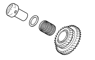
Coat the reverse idler gear, needle roller bearing, and reverse idler thrust washer with MP grease, and install them to the reverse idler gear shaft.
Tip:Make sure that the protruding part on the reverse idler thrust washer is fitted into the groove of the reverse idler shaft.
-
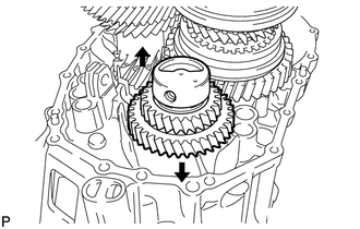
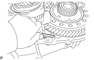
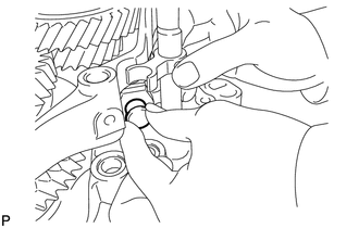
Install the reverse idler gear shaft by sliding and lifting it.
-
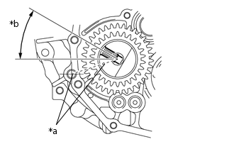
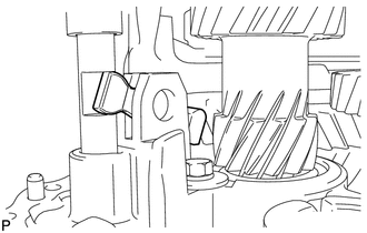
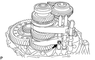
*a
Align the mark with the hole.
*b
30°
Align the mark of the reverse idler gear shaft with the hole of the bolt.
-
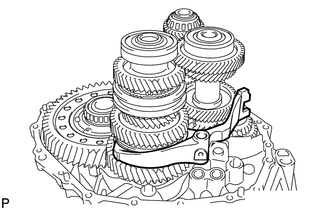
INSTALL REVERSE SHIFT FORK
-
Install the reverse shift fork to the No. 2 output shaft assembly.
-
INSTALL NO. 3 GEAR SHIFT FORK
-
Install the No. 3 gear shift fork to the No. 2 output shaft assembly.
-
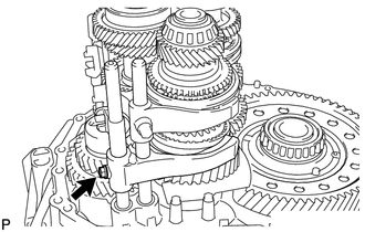
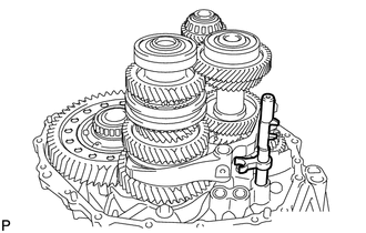
INSTALL 5TH AND 6TH SHIFT FORK SHAFT
-
Install the 5th and 6th shift fork shaft to the front transaxle case.
-
Coat the bolt with sealant.
Sealant
Toyota Genuine Adhesive 1344, Three Bond 1344 or equivalent
Install the bolt to the No. 3 gear shift fork.
19.6 N*m
200 kgf*cm
14 ft.*lbf
-
INSTALL REVERSE SHIFT FORK SHAFT
-
Install the reverse shift fork shaft to the front transaxle case.
-
Coat the bolt with sealant.
Sealant
Toyota Genuine Adhesive 1344, Three Bond 1344 or equivalent
Install the bolt to the reverse shift fork.
19.6 N*m
200 kgf*cm
14 ft.*lbf
-
INSTALL SHIFT ARM
-
Install the shift arm to the front transaxle case.
-
INSTALL NO. 1 GEAR SHIFT FORK
-
Install the No. 1 gear shift fork to the No. 1 output shaft assembly.
-
INSTALL NO. 5 GEAR SHIFT FORK SHAFT
-
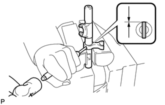
Install the No. 3 gear shift head to the No. 5 gear shift fork shaft.
Using a 5 mm pin punch and hammer, drive a new slotted spring pin into the No. 3 gear shift head.
Depth
-0.5 to 0.5 mm (-0.0197 to 0.0197 in.)
-
Install the No. 5 gear shift fork shaft to the front transaxle case.
-
Install the shift arm to the No. 5 gear shift fork shaft.
-
Install the pin to the shift arm.
-
Using a brass bar and hammer, install a new E-ring to the pin.
-
INSTALL NO. 2 GEAR SHIFT FORK
-
Install the No. 2 gear shift fork to the No. 1 output shaft assembly.
-
INSTALL 3RD AND 4TH SHIFT FORK SHAFT
-
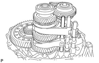
Install the No. 2 gear shift head to the 3rd and 4th shift fork shaft.
Install the 3rd and 4th shift fork shaft to the front transaxle case.
-
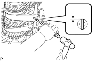
Using a 5 mm pin punch and hammer, drive a new slotted spring pin into the No. 2 gear shift fork.
Drive in Depth
-0.5 to 0.5 mm (-0.0197 to 0.0197 in.)
-
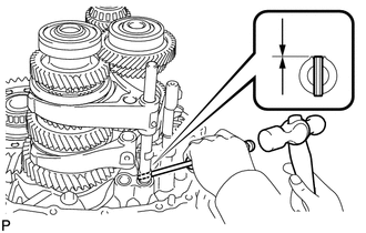
Using a 5 mm pin punch and hammer, drive a new slotted spring pin into the No. 2 gear shift head.
Drive in Depth
-0.5 to 0.5 mm (-0.0197 to 0.0197 in.)
-
INSTALL 1ST AND 2ND SHIFT FORK SHAFT
-
Install the 1st and 2nd shift fork shaft to the front transaxle case.
-
Coat the bolt with sealant.
Sealant
Toyota Genuine Adhesive 1344, Three Bond 1344 or equivalent
Install the bolt to the No. 1 gear shift fork.
19.6 N*m
200 kgf*cm
14 ft.*lbf
-
INSTALL TRANSMISSION OIL SEPARATOR
-
Install the transmission oil separator to the manual transmission case with the 2 bolts.
8.5 N*m
87 kgf*cm
75 in.*lbf
-
INSTALL NO. 1 OIL RECEIVER PIPE
-
Install the No. 1 oil receiver pipe to the manual transmission case.
Note:Do not damage the No. 1 oil receiver pipe.
-
INSTALL MANUAL TRANSMISSION CASE
Clean the seal packing attached on the manual transmission case and front transaxle case using a scraper and wire brush. Then remove the oil with non-residue solvent.
Note:Do not scratch the fitting surface.
-
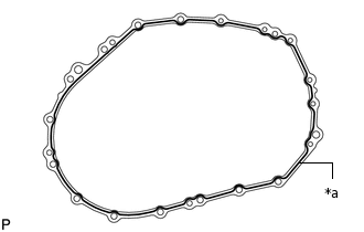
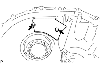
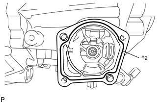
*a
FIPG
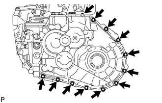
Apply FIPG to the manual transmission case as shown in the illustration.
FIPG
Toyota Genuine Seal Packing 1281, Three Bond 1281 or equivalent
Note:Install the parts within 10 minutes of application. Otherwise, the packing (FIPG) material must be removed and reapplied.
-
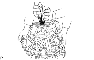
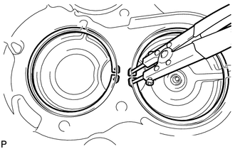
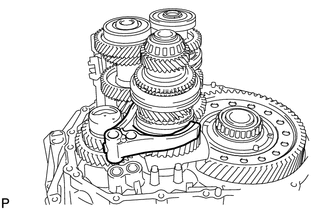
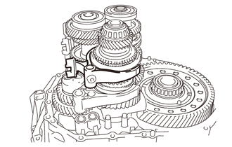
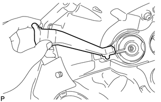
Use 2 snap ring pliers to keep the snap rings stretched and install the manual transmission case.
-
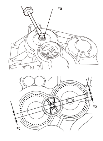
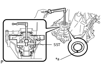
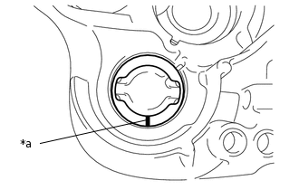
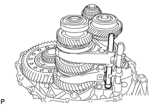
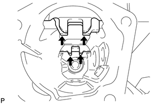
*a
Service Hole
*b
8.5 mm (0.335 in. )
*c
9.3 mm (0.366 in. )
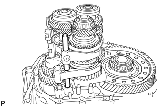
Install the bolt to the No. 1 output shaft assembly and lift the bolt from the service hole as shown in the illustration. Make sure that the snap rings are positioned correctly in the bearing grooves by checking that the distances between the centers of the snap ring holes are as shown in the illustration.
-
Install the manual transmission case to the front transaxle case with the 12 bolts.
29.4 N*m
300 kgf*cm
22 ft.*lbf
-
Install the 6 bolts to the manual transaxle case side.
29.4 N*m
300 kgf*cm
22 ft.*lbf
INSTALL REVERSE IDLER GEAR SHAFT BOLT
-
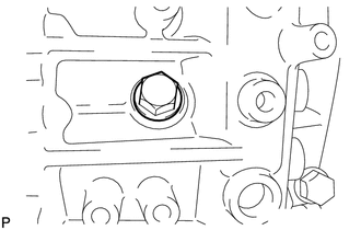
Coat the reverse idler gear shaft bolt with sealant.
Sealant
Toyota Genuine Adhesive 1344, Three Bond 1344 or equivalent
Install a new gasket and the reverse idler gear shaft bolt to the manual transmission case.
80 N*m
816 kgf*cm
59 ft.*lbf
-
INSTALL SHIFT DETENT BALL
-
Coat the 4 detent ball plugs with sealant.
Sealant
Toyota Genuine Adhesive 1344, Three Bond 1344 or equivalent
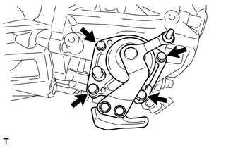
Install the 4 shift detent balls, 4 springs, 4 spring seats and 4 detent ball plugs using a 6 mm hexagon wrench.
22.4 N*m
228 kgf*cm
17 ft.*lbf
-
INSTALL MANUAL TRANSMISSION CASE PLUG
Clean the seal packing attached on the manual transmission case using a scraper and wire brush. Then remove the oil with non-residue solvent or equivalent.
Note:Do not scratch the fitting surface.
-
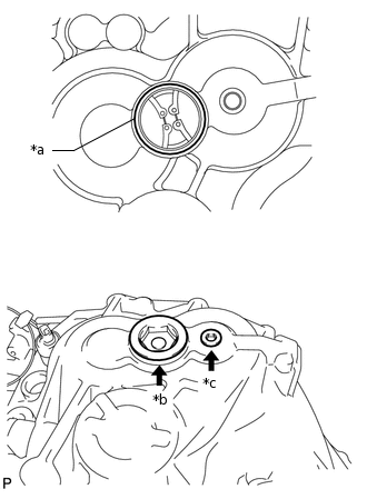
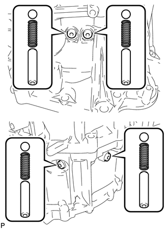
*a
FIPG
*b
Case plug A
*c
Case plug B
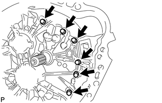
Apply FIPG to the manual transmission case as shown in the illustration.
FIPG
Toyota Genuine Seal Packing 1281, Three Bond 1281 or equivalent
Note:Install the parts within 10 minutes of application. Otherwise, the packing (FIPG) material must be removed and reapplied.
Coat the transmission case plugs with sealant.
Sealant
Toyota Genuine Adhesive 1344, Three Bond 1344 or equivalent
Install the manual transmission case plugs to the manual transmission case.
Case Plug A
55 N*m
561 kgf*cm
41 ft.*lbf
Case Plug B
22.4 N*m
228 kgf*cm
17 ft.*lbf
INSTALL O-RING
-
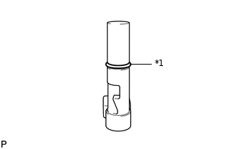
*1
O-ring
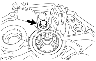
Coat a new O-ring with the MP grease, and install it to the shift and select pin.
-
INSTALL SHIFT AND SELECT PIN
-
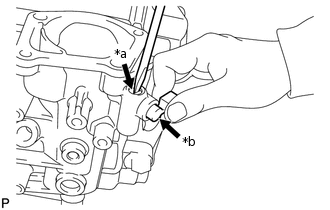
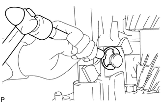
*a
Press and hold
*b
Push in the shift and select pin.
Install the spring.
While pressing in the shift and select pin in as far as it will go, push in the shift and select pin to install it.
-
INSTALL MANUAL TRANSMISSION FILLER PLUG
-
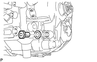
Install a new gasket and the manual transmission filler plug to the manual transmission case.
39.2 N*m
400 kgf*cm
29 ft.*lbf
-
INSTALL DRAIN PLUG
-
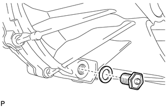
Install a new gasket and the drain plug to the front transaxle case.
39.2 N*m
400 kgf*cm
29 ft.*lbf
-
INSTALL TRANSMISSION CASE OIL SEAL
Coat a new transmission case oil seal lip with MP grease.
-
Using SST and a hammer, install the transmission case oil seal.
09608-10010
09950-70010
09951-07200
Drive in Depth
-0.5 to 0.5 mm (-0.0197 to 0.0197 in.)
Note:Do not damage the transmission case oil seal lip.
INSTALL TRANSAXLE CASE OIL SEAL
Coat a new transaxle case oil seal lip with MP grease.
-
Using SST and a hammer, install the transaxle case oil seal.
09608-32010
09950-70010
09951-07200
Drive in Depth
-0.5 to 0.5 mm (-0.0197 to 0.0197 in.)
Note:Do not damage the transaxle case oil seal lip.
INSTALL SHIFT AND SELECT LEVER ASSEMBLY
-
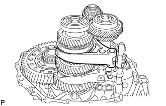
Align the 4 shift fork shafts as shown in the illustration.
Clean the seal packing attached on the manual transmission case and control shaft cover using a scraper and wire brush. Then remove the oil with non-residue solvent.
Note:Do not scratch the fitting surface.
-
*a
FIPG
Apply FIPG to the manual transmission case as shown in the illustration.
FIPG
Toyota Genuine Seal Packing 1281, Three Bond 1281 or equivalent
Note:Install the parts within 10 minutes of application. Otherwise, the packing (FIPG) material must be removed and reapplied.
Coat the 4 bolts with sealant.
Sealant
Toyota Genuine Adhesive 1344, Three Bond 1344 or equivalent
-
Install the shift and select lever assembly to the manual transmission case with the 4 bolts.
18.6 N*m
190 kgf*cm
14 ft.*lbf
-
INSTALL SHIFT GATE PIN
-
Coat the shift gate pin with sealant.
Sealant
Toyota Genuine Adhesive 1344, Three Bond 1344 or equivalent
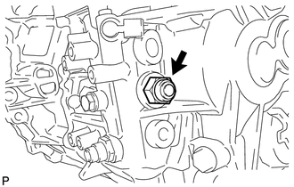
Install the shift gate pin to the manual transmission case.
30 N*m
306 kgf*cm
22 ft.*lbf
-
INSTALL NO. 2 LOCK BALL ASSEMBLY
-
Coat the No. 2 lock ball assembly with sealant.
Sealant
Toyota Genuine Adhesive 1344, Three Bond 1344 or equivalent
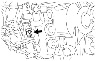
Install the No. 2 lock ball assembly to the manual transmission case.
29.4 N*m
300 kgf*cm
22 ft.*lbf
-
INSTALL NO. 1 LOCK BALL ASSEMBLY
-
Coat the No. 1 lock ball assembly with sealant.
Sealant
Toyota Genuine Adhesive 1344, Three Bond 1344 or equivalent
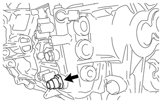
Install the No. 1 lock ball assembly to the manual transmission case.
39.2 N*m
400 kgf*cm
29 ft.*lbf
-
INSTALL NEUTRAL POSITION SWITCH
-
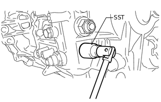
Using SST, install a new gasket and the neutral position switch to the manual transmission case.
09816-30010
40.2 N*m
410 kgf*cm
30 ft.*lbf
-
INSTALL BACK-UP LAMP SWITCH ASSEMBLY
-
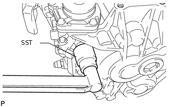
Using SST, install a new gasket and the back-up light switch assembly to the manual transmission case.
09816-30010
40.2 N*m
410 kgf*cm
30 ft.*lbf
-
INSTALL SELECTING BELL CRANK ASSEMBLY
-
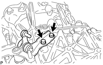
Install the selecting bell crank assembly to the manual transmission case with the 2 bolts.
20 N*m
204 kgf*cm
15 ft.*lbf
-
INSTALL CONTROL CABLE BRACKET
-
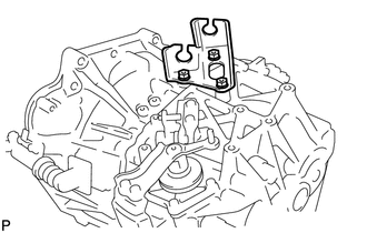
Install the control cable bracket to the manual transaxle assembly with the 3 bolts.
17 N*m
173 kgf*cm
13 ft.*lbf
-
INSTALL CLUTCH RELEASE FORK BOOT
INSTALL RELEASE FORK SUPPORT
INSTALL CLUTCH RELEASE BEARING ASSEMBLY
INSTALL CLUTCH RELEASE FORK SUB-ASSEMBLY