ELECTRIC PARKING BRAKE SYSTEM TERMINALS OF ECU
-
CHECK SKID CONTROL ECU (BRAKE ACTUATOR ASSEMBLY)
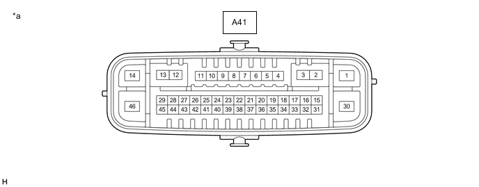
*a Component without harness connected
(Skid Control ECU (Brake Actuator Assembly))
- -
-
Disconnect the A41 skid control ECU (brake actuator assembly) connectors.
-
Measure the voltage and resistance according to the value (s) in the table below.
Terminal No. (Symbol) Wiring Color Terminal Description Condition Specified Condition A41-14 (+BS) - Body ground L Parking brake motor (parking brake actuator assembly) power supply Always 11 to 14 V A41-45 (IG1) - Body ground V*1
B*2
IG power supply Engine switch on (IG) 11 to 14 V*1
9.5 to 14 V*2
A41-1 (GND1) - Body ground W-B Ground Always Below 1 Ω A41-30 (GND2) - Body ground W-B Ground Always Below 1 Ω A41-13 (MRR+) - Body ground Y Parking brake motor RH (parking brake actuator assembly RH) (+) - - A41-12 (MRR-) - Body ground R Parking brake motor RH (parking brake actuator assembly RH) (-) - - A41-3 (MRL+) - Body ground B Parking brake motor LH (parking brake actuator assembly LH) (+) - - A41-2 (MRL-) - Body ground L Parking brake motor LH (parking brake actuator assembly LH) (-) - - A41-40 (LPA) - Body ground Y AUTO indicator light - - A41-15 (TX) - Body ground Y Combination meter assembly communication signal - - A41-38 (POL) - Body ground L Electric parking brake switch indicator light - - A41-36 (LCK1) - Body ground G Electric parking brake switch assembly lock 1 - - A41-23 (LCK2) - Body ground LG Electric parking brake switch assembly lock 2 - - A41-31 (REL1) - Body ground W Electric parking brake switch assembly release 1 - - A41-39 (REL2) - Body ground R Electric parking brake switch assembly release 2 - -
-
*1: w/o Stop and Start System
-
*2: w/ Stop and Start System
-
-