THEFT DETERRENT SYSTEM ECU Power Source Circuit
DESCRIPTION
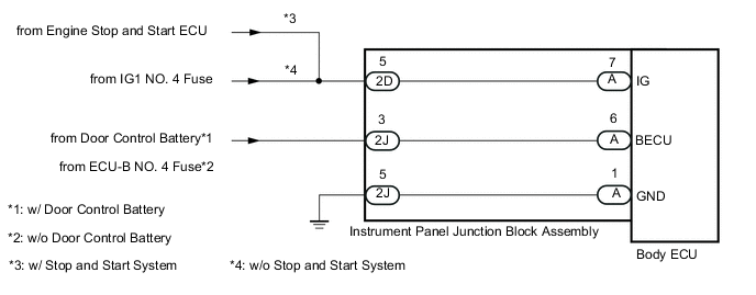
This circuit provides power to operate the body ECU.
WIRING DIAGRAM
CAUTION / NOTICE / HINT
Note
-
Inspect the fuses for circuits related to this system before performing the following procedure.
-
w/ Door Control Battery:
As the door control battery is installed between the vehicle battery and body ECU, first perform the inspections to confirm that there are no malfunctions in the power source circuit for the body ECU before performing this troubleshooting procedure.
-
w/ Automatic Light Control System:
If the body ECU has been replaced, it is necessary to initialize the body ECU.
PROCEDURE
-
CHECK HARNESS AND CONNECTOR (POWER SOURCE CIRCUIT)
-
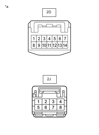
*a Front view of wire harness connector
(to Instrument Panel Junction Block Assembly)
Disconnect the instrument panel junction block assembly connectors.
-
Measure the resistance according to the value(s) in the table below.
Standard Resistance Tester Connection Condition Specified Condition 2J-5 - Body ground Always Below 1 Ω -
Measure the voltage according to the value(s) in the table below.
Standard Voltage Tester Connection Condition Specified Condition 2D-5 - Body ground Ignition switch ON 11 to 14 V 2J-3 - Body ground Always 11 to 14 V Result Proceed to OK NG
NG 
REPAIR OR REPLACE HARNESS OR CONNECTOR
OK 
-
-
INSPECT INSTRUMENT PANEL JUNCTION BLOCK ASSEMBLY
-
Remove the body ECU.
-
for LHD:
-
for RHD:
-
-
Measure the resistance according to the value(s) in the table below.
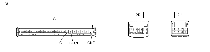
*a Component without harness connected
(Instrument Panel Junction Block Assembly)
- - Standard Resistance Tester Connection Condition Specified Condition 2J-5 - A-1 (GND) Always Below 1 Ω 2D-5 - A-7 (IG) Always Below 1 Ω 2J-3 - A-6 (BECU) Always Below 1 Ω Result Proceed to OK NG (for LHD) NG (for RHD)
OK
PROCEED TO NEXT SUSPECTED AREA SHOWN IN PROBLEM SYMPTOMS TABLE Click here
NG (for LHD)
REPLACE INSTRUMENT PANEL JUNCTION BLOCK ASSEMBLY Click here
NG (for RHD)
REPLACE INSTRUMENT PANEL JUNCTION BLOCK ASSEMBLY Click here
-