TURBOCHARGER (w/o EGR Cooler) INSTALLATION
-
CLEAN TURBOCHARGER SUB-ASSEMBLY
-
INSTALL TURBOCHARGER SUB-ASSEMBLY
-
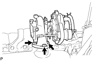
Temporarily install a new gasket and the turbocharger with 3 new nuts.
Tech Tips
When installing the turbo oil pipe, loosely tighten the 3 nuts so that the turbocharger and cylinder head can be aligned easily.
-
Temporarily install the turbo oil pipe and manifold stay.
Tech Tips
Wash the oil pipe before installing it.
-
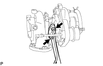
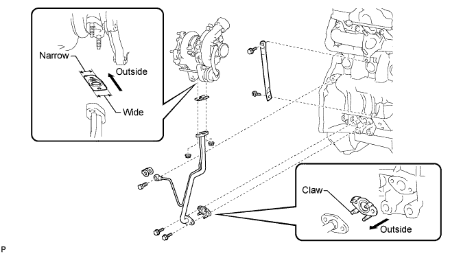
Temporarily install a new gasket and the oil pipe with the 2 nuts, but only loosely install the nuts.
Note
The notch (wide part) of the gasket must face the engine.
-
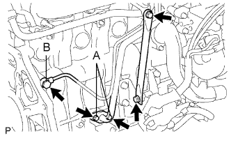
Temporarily install a new gasket and the oil pipe with the 2 bolts (labeled: A), but only loosely install the bolts.
Note
The claws of the gasket must face the pipe.
-
Temporarily install a new gasket and the oil pipe with the union bolt (labeled: B), but only loosely install the union bolt.
-
Temporarily install the stay with the 2 bolts.
Tech Tips
The stay's indented area must face the turbocharger.
-
-
Tighten the bolts and nuts.
-
Tighten the 3 nuts of the turbocharger.
- Torque:
- 52 N*m { 530 kgf*cm, 38 ft.*lbf }
-
Tighten the 2 nuts of the oil pipe.
- Torque:
- 13 N*m { 133 kgf*cm, 10 ft.*lbf }
-
Tighten the 2 bolts of the oil pipe.
- Torque:
- 12 N*m { 122 kgf*cm, 9 ft.*lbf }
-
Tighten the union bolt.
- Torque:
- 26 N*m { 265 kgf*cm, 19 ft.*lbf }
-
Tighten the 2 bolts of the stay.
- Torque:
- 19 N*m { 194 kgf*cm, 14 ft.*lbf }
-
-
-
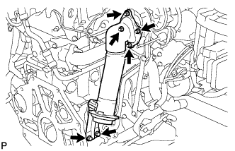
INSTALL TURBINE OUTLET ELBOW
-
Temporarily install a new gasket and the outlet elbow (with turbocharger stay) to the turbocharger with the 4 nuts.
-
Temporarily install the stay with the 2 bolts.
-
Tighten the 4 nuts of the turbocharger.
- Torque:
- 26 N*m { 265 kgf*cm, 19 ft.*lbf }
-
Tighten the 2 bolts of the stay.
- Torque:
- 24 N*m { 245 kgf*cm, 18 ft.*lbf }
-
-
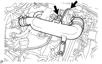
INSTALL NO. 2 AIR CLEANER PIPE SUB-ASSEMBLY
-
Connect the pipe (with the 2 air hoses) and install the bolt.
- Torque:
- 20 N*m { 204 kgf*cm, 15 ft.*lbf }
-
Tighten the 2 clamps of the No. 1 and No. 2 air hoses.
- Torque:
- 6.5 N*m { 66 kgf*cm, 57 in.*lbf }
-
Connect the vacuum hose to the gas filter.
-
Connect the manifold absolute pressure sensor connector.
-
-
INSTALL VENTILATION HOSE HEAT INSULATOR
-
Install the insulator with the 2 bolts.
- Torque:
- 12 N*m { 122 kgf*cm, 9 ft.*lbf }
-
-
INSTALL AIR CLEANER ASSEMBLY
-
w/o Mass Air Flow Meter:
-
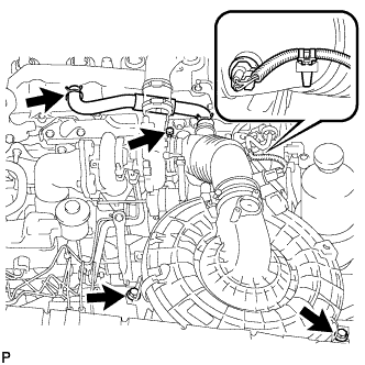
Connect the air cleaner hose.
-
Install the air cleaner with the 2 bolts.
- Torque:
- 14 N*m { 143 kgf*cm, 10 ft.*lbf }
-
Tighten the clamp.
-
Install the clamp and connect the intake air temperature sensor connector.
-
Connect the ventilation hose.
-
Slide the clamp to the connection of the hose.
-
-
w/ Mass Air Flow Meter:
-
Connect the air cleaner hose.
-
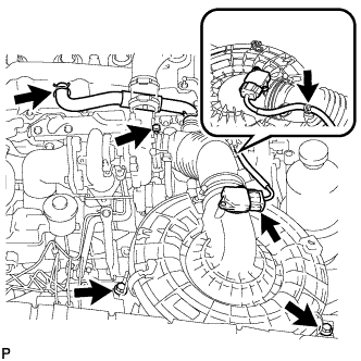
Install the air cleaner with the 2 bolts.
- Torque:
- 14 N*m { 143 kgf*cm, 10 ft.*lbf }
-
Connect the connector to the mass air flow meter.
-
Tighten the hose clamp.
-
-
-
INSTALL FRONT EXHAUST PIPE ASSEMBLY
-
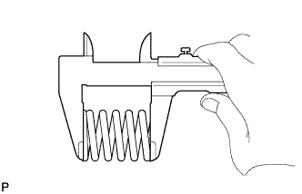
Using a vernier caliper, measure the free length of the compression spring.
Minimum length 40 mm (1.57 in.) If the free length is less than the minimum, replace the compression spring.
-
Install the front pipe to the pipe support.
-
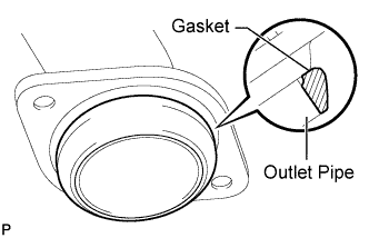
Install a new gasket to the outlet pipe.
Note
-
Be careful with the installation direction of the gasket.
-
Do not reuse the gasket.
-
To ensure a proper seal, do not use the front pipe to force the gasket onto the outlet pipe.
Tech Tips
Using a plastic-faced hammer, uniformly strike the gasket so that the gasket and outlet pipe are properly fit.
-
-
Install the front pipe with the 2 compression springs and 2 bolts. Alternately tighten the bolts in several passes.
- Torque:
- 43 N*m { 438 kgf*cm, 32 ft.*lbf }
CAUTION:
Do not reuse the gasket.
-
-
CONNECT CABLE TO NEGATIVE BATTERY TERMINAL
-
CHECK FOR ENGINE OIL LEAKS
-
CHECK FOR EXHAUST LEAKS
If gas is leaking, tighten the problem areas to stop the leak. Replace damaged parts as necessary.
-
INSTALL FRONT FENDER APRON SEAL UPPER
-
Install the apron seal with the 5 clips.
-
-
INSTALL FRONT FENDER SEAL
-
Install the fender seal with the 5 clips.
-
-
INSTALL FRONT WHEEL RH
-
INSTALL NO. 1 ENGINE UNDER COVER
-
Install the cover with the 4 bolts.
- Torque:
- 28 N*m { 286 kgf*cm, 21 ft.*lbf }
-
-
PERFORM INITIALIZATION
-
Perform initialization Click here.
Note
Certain systems need to be initialized after disconnecting and reconnecting the cable from the negative (-) battery terminal.
-