SFI SYSTEM, Diagnostic DTC:P0037, P0038
| DTC Code | DTC Name |
|---|---|
| P0037 | Oxygen Sensor Heater Control Circuit Low (Bank 1 Sensor 2) |
| P0038 | Oxygen Sensor Heater Control Circuit High (Bank 1 Sensor 2) |
CAUTION / NOTICE / HINT
Tech Tips
-
Sensor 1 refers to the sensor mounted before the Three-Way Catalytic Converter (TWC) and is located near the engine assembly.
-
Sensor 2 refers to the sensor mounted after the TWC and is located far from the engine assembly.
DESCRIPTION
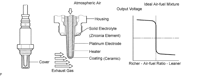
In order to obtain a high purification rate of the carbon monoxide (CO), hydrocarbon (HC) and nitrogen oxide (NOx) components in the exhaust gas, a TWC is used. For the most efficient use of the TWC, the air-fuel ratio must be precisely controlled so that it is always close to the stoichiometric air-fuel level. To help the ECM to deliver accurate air-fuel ratio control, a heated oxygen sensor is used.
The heated oxygen sensor is located behind the TWC, and detects the oxygen concentration in the exhaust gas. Since the sensor is integrated with the heater that heats the sensing portion, it is possible to detect the oxygen concentration even when the intake air volume is low (the exhaust gas temperature is low).
When the air-fuel ratio becomes lean, the oxygen concentration in the exhaust gas is rich. The heated oxygen sensor informs the ECM that the post-TWC air-fuel ratio is lean (low voltage, i.e. less than 0.45 V).
Conversely, when the air-fuel ratio is richer than the stoichiometric air-fuel level, the oxygen concentration in the exhaust gas becomes lean. The heated oxygen sensor informs the ECM that the post-TWC air-fuel ratio is rich (high voltage, i.e. more than 0.45 V). The heated oxygen sensor has the property of changing its output voltage drastically when the air-fuel ratio is close to the stoichiometric level.
The ECM uses the supplementary information from the heated oxygen sensor to determine whether the air-fuel ratio after the TWC is rich or lean, and adjusts the fuel injection time accordingly. Thus, if the heated oxygen sensor is working improperly due to internal malfunctions, the ECM is unable to compensate for deviations in the primary air-fuel ratio control.
Tech Tips
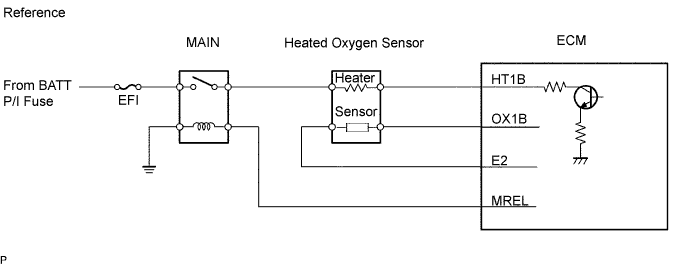
The ECM provides a pulse width modulated control circuit to adjust current through the heater. The heated oxygen sensor heater circuit uses a relay on the +B side of the circuit.
| DTC No. | DTC Detection Condition | Trouble Area |
|---|---|---|
| P0037 | Heated current is 0.3 A or less when heater operates (1 trip detection logic) |
|
| P0038 | Heated current exceeds 2 A when heater operates (1 trip detection logic) |
|
MONITOR DESCRIPTION
The sensing portion of the heated oxygen sensor has a zirconia element which is used to detect oxygen concentration in the exhaust. If the zirconia element is at the proper temperature and the difference of the oxygen concentration between the inside and outside surface of the sensor is large, the zirconia element will generate voltage signals. In order to increase the oxygen concentration detecting capacity in the zirconia element, the ECM supplements the heat from the exhaust with the heat from the heating element inside the sensor. When current in the sensor is out of the standard operating range, the ECM interprets this as a fault in the heated oxygen sensor and sets a DTC.
Example:
The ECM will set a high-current DTC if the current in the sensor is more than 2 A when the heater is on. Similarly, the ECM will set a low-current DTC if the current is less than 0.3 A when the heater is on.
WIRING DIAGRAM
Refer to DTC P0136 Click here.
INSPECTION PROCEDURE
Tech Tips
Read freeze frame data using the intelligent tester. Freeze frame data records the engine conditions when malfunctions are detected. When troubleshooting, freeze frame data can help determine if the vehicle was moving or stationary, if the engine was warmed up or not, if the air-fuel ratio was lean or rich, and other data from the time the malfunction occurred.
PROCEDURE
-
INSPECT HEATED OXYGEN SENSOR (HEATER RESISTANCE)
-
Disconnect the H7 sensor connector.
-
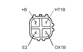
Measure the resistance of the heated oxygen sensor.
Standard Tester Connection Condition Specified Condition 1 (HT1B) - 2 (+B) 20°C (68°F) 11 to 16 Ω 1 (HT1B) - 4 (E2) Always 10 kΩ or higher
NG 
REPLACE HEATED OXYGEN SENSOR
OK 
-
-
INSPECT INTEGRATION NO.1 RELAY (MAIN RELAY)
-
Remove the integration relay from the engine room junction block.
-
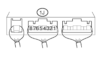
Measure the voltage of the MAIN relay.
Standard Tester Connection Condition Specified Condition 1J-5 - Body ground Ignition switch ON 10 to 14 V
NG
REPLACE INTEGRATION NO.1 RELAY
OK
-
-
INSPECT ECM (HT1B VOLTAGE)
-
Turn the ignition switch ON.
-
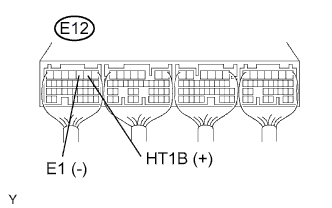
Measure the voltage of the E12 ECM connector.
Standard voltage Tester Connection Specified Condition E12-2 (HT1B) - E12-3 (E1) 9 to 14 V
OK
REPLACE ECM
NG
-
-
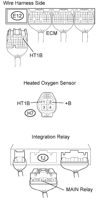
CHECK WIRE HARNESS (HEATED OXYGEN SENSOR - ECM, INTEGRATION RELAY (MAIN RELAY))
-
Disconnect the H7 sensor connector.
-
Disconnect the E12 ECM connector.
-
Disconnect the 1J connector from the engine room junction block.
-
Measure the resistance of the wire harness side connectors.
Standard resistance Tester Connection Specified Condition H7-1 (HT1B) - E12-2 (HT1B) Below 1 Ω H7-2 (+B) - 1J-5 Below 1 Ω H7-1 (HT1B) or E12-2 (HT1B) - Body ground 10 kΩ or higher H7-2 (+B) or 1J-5 - Body ground 10 kΩ or higher
NG
REPAIR OR REPLACE HARNESS AND CONNECTOR
OK 
REPLACE ECM
-