AUDIO AND VISUAL SYSTEM(for Radio and Display Type), Diagnostic DTC:B1579
| DTC Code | DTC Name |
|---|---|
| B1579 | Voice Recognition Microphone Disconnected |
DESCRIPTION
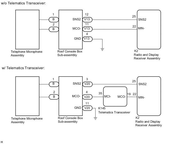
The radio and display receiver assembly, roof console box sub-assembly and telephone microphone assembly are connected to each other using the microphone connection detection signal lines.
This DTC is stored when a microphone connection detection signal line is disconnected.
| DTC No. | Detection Item | DTC Detection Condition | Trouble Area |
|---|---|---|---|
| B1579 | Voice Recognition Microphone Disconnected | Microphone signal is lost |
|
-
*: w/ Telematics Transceiver
WIRING DIAGRAM
Figure 1. w/ Sliding Roof
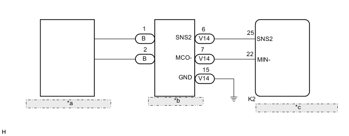
| *a | Telephone Microphone Assembly |
| *b | Roof Console Box Sub-assembly |
| *c | Radio and Display Receiver Assembly |
Figure 2. w/o Sliding Roof
CAUTION / NOTICE / HINT
Note
-
Depending on the parts that are replaced during vehicle inspection or maintenance, performing initialization, registration or calibration may be needed. Refer to Precaution for Audio and Visual System.
-
When replacing the radio and display receiver assembly, always replace it with a new one. If a radio and display receiver assembly which was installed to another vehicle is used, the following may occur:
-
A communication malfunction DTC may be stored.
-
The radio and display receiver assembly may not operate normally.
PROCEDURE
-
INSPECT RADIO AND DISPLAY RECEIVER ASSEMBLY
-
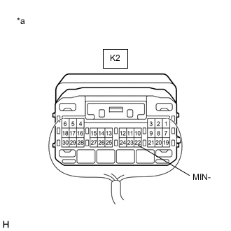
*a Component with harness connected
(Radio and Display Receiver Assembly)
Measure the resistance according to the value(s) in the table below.
Standard Resistance Tester Connection Condition Specified Condition K2-22 (MIN-) - Body ground Always Below 1 Ω Result Result Proceed to OK (w/ Sliding Roof) A OK (w/o Sliding Roof and w/o Telematics Transceiver) B OK (w/o Sliding Roof and w/ Telematics Transceiver) C NG D
B 
CHECK HARNESS AND CONNECTOR (RADIO AND DISPLAY RECEIVER ASSEMBLY - ROOF CONSOLE BOX SUB-ASSEMBLY) Click here
C
CHECK HARNESS AND CONNECTOR (TELEMATICS TRANSCEIVER - ROOF CONSOLE BOX SUB-ASSEMBLY) Click here
D 
REPLACE RADIO AND DISPLAY RECEIVER ASSEMBLY Click here
A 
-
-
CHECK HARNESS AND CONNECTOR (RADIO AND DISPLAY RECEIVER ASSEMBLY - ROOF CONSOLE BOX SUB-ASSEMBLY)
-
Disconnect the K2 radio and display receiver assembly connector.
-
Disconnect the V14 roof console box sub-assembly connector.
-
Measure the resistance according to the value(s) in the table below.
Standard Resistance Tester Connection Condition Specified Condition K2-25 (SNS2) - V14-6 (SNS2) Always Below 1 Ω K2-22 (MIN-) - V14-7 (MCO-) Always Below 1 Ω K2-25 (SNS2) or V14-6 (SNS2) - Body ground Always 10 kΩ or higher K2-22 (MIN-) or V14-7 (MCO-) - Body ground Always 10 kΩ or higher Result Proceed to OK NG
NG
REPAIR OR REPLACE HARNESS OR CONNECTOR
OK
-
-
INSPECT ROOF CONSOLE BOX SUB-ASSEMBLY
-
Remove the roof console box sub-assembly.
-
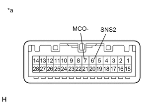
*a Component without harness connected
(Roof Console Box Sub-assembly)
Measure the resistance according to the value(s) in the table below.
Standard Resistance Tester Connection Condition Specified Condition 6 (SNS2) - 7 (MCO-) Always Below 1 Ω Result Proceed to OK NG
OK
REPLACE RADIO AND DISPLAY RECEIVER ASSEMBLY Click here
NG
-
-
INSPECT ROOF CONSOLE BOX SUB-ASSEMBLY
-
Remove the roof console box sub-assembly.
-
Disconnect the B telephone microphone assembly connector.
-
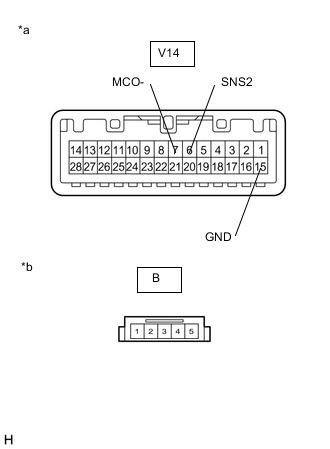
*a Component without harness connected
(Roof Console Box Sub-assembly (No. 1 Roof Wire Side))
*b Component without harness connected
(Roof Console Box Sub-assembly (Telephone Microphone Assembly Side))
Measure the resistance according to the value(s) in the table below.
Standard Resistance Tester Connection Condition Specified Condition B-1 - V14-6 (SNS2) Always Below 1 Ω B-2 - V14-7 (MCO-) Always Below 1 Ω B-1 or V14-6 (SNS2) - V14-15 (GND) Always 10 kΩ or higher B-2 or V14-7 (MCO-) - V14-15 (GND) Always 10 kΩ or higher Result Proceed to OK NG
OK
REPLACE TELEPHONE MICROPHONE ASSEMBLY Click here
NG
REPLACE ROOF CONSOLE BOX SUB-ASSEMBLY Click here
-
-
CHECK HARNESS AND CONNECTOR (RADIO AND DISPLAY RECEIVER ASSEMBLY - ROOF CONSOLE BOX SUB-ASSEMBLY)
-
Disconnect the K2 radio and display receiver assembly connector.
-
Disconnect the V13 roof console box sub-assembly connector.
-
Measure the resistance according to the value(s) in the table below.
Standard Resistance Tester Connection Condition Specified Condition K2-25 (SNS2) - V13-12 (SNS2) Always Below 1 Ω K2-22 (MIN-) - V13-11 (MCO-) Always Below 1 Ω K2-25 (SNS2) or V13-12 (SNS2) - Body ground Always 10 kΩ or higher K2-22 (MIN-) or V13-11 (MCO-) - Body ground Always 10 kΩ or higher Result Proceed to OK NG
NG
REPAIR OR REPLACE HARNESS OR CONNECTOR
OK
-
-
INSPECT ROOF CONSOLE BOX SUB-ASSEMBLY
-
Remove the roof console box sub-assembly.
-
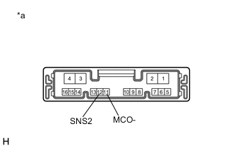
*a Component without harness connected
(Roof Console Box Sub-assembly)
Measure the resistance according to the value(s) in the table below.
Standard Resistance Tester Connection Condition Specified Condition 12 (SNS2) - 11 (MCO-) Always Below 1 Ω Result Proceed to OK NG
OK
REPLACE RADIO AND DISPLAY RECEIVER ASSEMBLY Click here
NG
-
-
INSPECT ROOF CONSOLE BOX SUB-ASSEMBLY
-
Remove the roof console box sub-assembly.
-
Disconnect the B telephone microphone assembly connector.
-
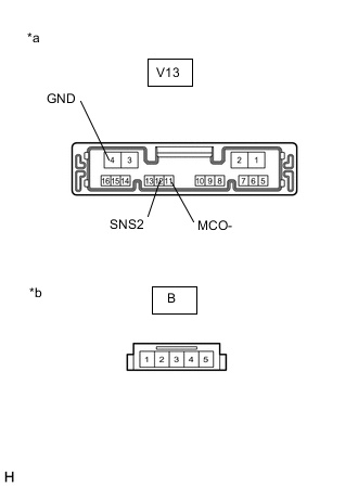
*a Component without harness connected
(Roof Console Box Sub-assembly (No. 1 Roof Wire Side))
*b Component without harness connected
(Roof Console Box Sub-assembly (Telephone Microphone Assembly Side))
Measure the resistance according to the value(s) in the table below.
Standard Resistance Tester Connection Condition Specified Condition B-1 - V13-12 (SNS2) Always Below 1 Ω B-2 - V13-11 (MCO-) Always Below 1 Ω B-1 or V13-12 (SNS2) - V13-4 (GND) Always 10 kΩ or higher B-2 or V13-11 (MCO-) - V13-4 (GND) Always 10 kΩ or higher Result Proceed to OK NG
OK
REPLACE TELEPHONE MICROPHONE ASSEMBLY Click here
NG
REPLACE ROOF CONSOLE BOX SUB-ASSEMBLY Click here
-
-
CHECK HARNESS AND CONNECTOR (TELEMATICS TRANSCEIVER - ROOF CONSOLE BOX SUB-ASSEMBLY)
-
Disconnect the K145 telematics transceiver connector.
-
Disconnect the V20 roof console box sub-assembly connector.
-
Measure the resistance according to the value(s) in the table below.
Standard Resistance Tester Connection Condition Specified Condition K145-35 (MCI-) - V20-4 (MCO-) Always Below 1 Ω K145-35 (MCI-) or V20-4 (MCO-) - Body ground Always 10 kΩ or higher Result Proceed to OK NG
NG
REPAIR OR REPLACE HARNESS OR CONNECTOR
OK
-
-
CHECK HARNESS AND CONNECTOR (RADIO AND DISPLAY RECEIVER ASSEMBLY - TELEMATICS TRANSCEIVER)
-
Disconnect the K2 radio and display receiver assembly connector.
-
Disconnect the K145 telematics transceiver connector.
-
Measure the resistance according to the value(s) in the table below.
Standard Resistance Tester Connection Condition Specified Condition K2-22 (MIN-) - K145-19 (MCO-) Always Below 1 Ω K2-22 (MIN-) or K145-19 (MCO-) - Body ground Always 10 kΩ or higher Result Proceed to OK NG
NG
REPAIR OR REPLACE HARNESS OR CONNECTOR
OK
-
-
CHECK HARNESS AND CONNECTOR (RADIO AND DISPLAY RECEIVER ASSEMBLY - ROOF CONSOLE BOX SUB-ASSEMBLY)
-
Disconnect the K2 radio and display receiver assembly connector.
-
Disconnect the V20 roof console box sub-assembly connector.
-
Measure the resistance according to the value(s) in the table below.
Standard Resistance Tester Connection Condition Specified Condition K2-25 (SNS2) - V20-3 (SNS2) Always Below 1 Ω K2-25 (SNS2) or V20-3 (SNS2) - Body ground Always 10 kΩ or higher Result Proceed to OK NG
NG
REPAIR OR REPLACE HARNESS OR CONNECTOR
OK
-
-
INSPECT TELEMATICS TRANSCEIVER
-
Connect the K145 telematics transceiver connector.
-
Connect the K2 radio and display receiver assembly connector.
-
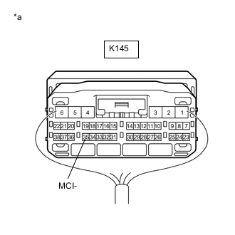
*a Component with harness connected
(Telematics Transceiver)
Measure the resistance according to the value(s) in the table below.
Standard Resistance Tester Connection Condition Specified Condition K145-35 (MCI-) - Body ground Always Below 1 Ω Result Proceed to OK NG
NG
REPLACE TELEMATICS TRANSCEIVER Click here
OK
-
-
INSPECT ROOF CONSOLE BOX SUB-ASSEMBLY
-
Remove the roof console box sub-assembly.
-
Connect the B telephone microphone assembly connector.
-
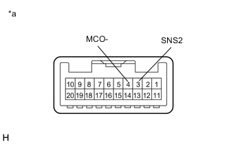
*a Component without harness connected
(Roof Console Box Sub-assembly)
Measure the resistance according to the value(s) in the table below.
Standard Resistance Tester Connection Condition Specified Condition 3 (SNS2) - 4 (MCO-) Always Below 1 Ω Result Proceed to OK NG
OK
REPLACE RADIO AND DISPLAY RECEIVER ASSEMBLY Click here
NG
-
-
INSPECT ROOF CONSOLE BOX SUB-ASSEMBLY
-
Remove the roof console box sub-assembly.
-
Disconnect the B telephone microphone assembly connector.
-
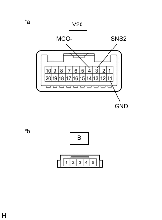
*a Component without harness connected
(Roof Console Box Sub-assembly (No. 1 Roof Wire Side))
*b Component without harness connected
(Roof Console Box Sub-assembly (Telephone Microphone Assembly Side))
Measure the resistance according to the value(s) in the table below.
Standard Resistance Tester Connection Condition Specified Condition B-1 - V20-3 (SNS2) Always Below 1 Ω B-2 - V20-4 (MCO-) Always Below 1 Ω B-1 or V20-3 (SNS2) - V20-11 (GND) Always 10 kΩ or higher B-2 or V20-4 (MCO-) - V20-11 (GND) Always 10 kΩ or higher Result Proceed to OK NG
OK
REPLACE TELEPHONE MICROPHONE ASSEMBLY Click here
NG
REPLACE ROOF CONSOLE BOX SUB-ASSEMBLY Click here
-