BLIND SPOT MONITOR SYSTEM, Diagnostic DTC:C1AB3
| DTC Code | DTC Name |
|---|---|
| C1AB3 | Short to GND in Outer Mirror Indicator(Slave) |
DESCRIPTION
This DTC is stored when the blind spot monitor sensor RH detects a ground short in the outer rear view mirror indicator RH.
| DTC No. | Detection Item | DTC Detection Condition | Trouble Area | Note |
|---|---|---|---|---|
| C1AB3 | Short to GND in Outer Mirror Indicator(Slave) |
Both of the following conditions are met:
|
|
- |
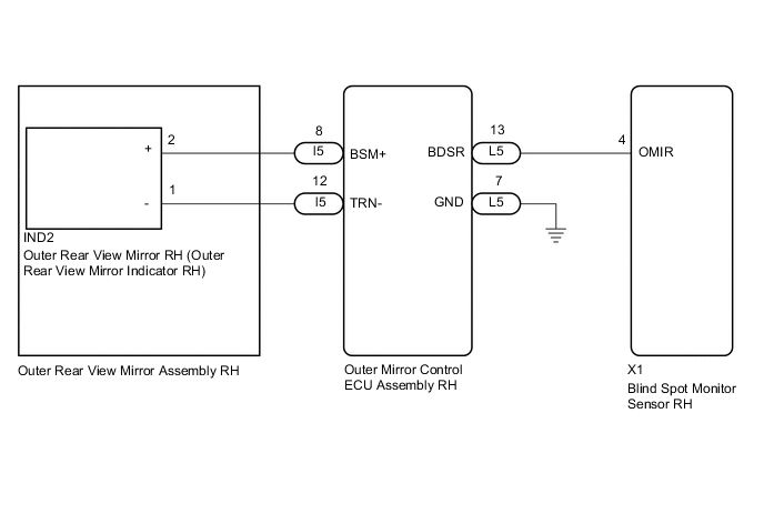
WIRING DIAGRAM
CAUTION / NOTICE / HINT
Note
When checking for DTCs, make sure that the blind spot monitor main switch (combination switch assembly) is on.
PROCEDURE
-
CHECK DTC
-
Clear the DTCs.
Body Electrical > Blind Spot Monitor Slave > Clear DTCs -
Recheck for DTCs and check if the same DTC is output again.
Body Electrical > Blind Spot Monitor Slave > Trouble CodesOK DTC C1AB3 is not output. Result Proceed to OK NG
OK 
USE SIMULATION METHOD TO CHECK Click here
NG 
-
-
CHECK HARNESS AND CONNECTOR (BLIND SPOT MONITOR SENSOR RH - OUTER MIRROR CONTROL ECU ASSEMBLY RH)
-
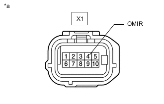
*a Front view of wire harness connector
(to Blind Spot Monitor Sensor RH)
Disconnect the blind spot monitor sensor RH connector.
-
Disconnect the L5 outer mirror control ECU assembly RH connector.
-
Measure the resistance according to the value(s) in the table below.
Standard Resistance Tester Connection Condition Specified Condition X1-4 (OMIR) - Body ground Always 10 kΩ or higher Result Proceed to OK NG
NG
REPAIR OR REPLACE HARNESS OR CONNECTOR
OK
-
-
CHECK OUTER REAR VIEW MIRROR ASSEMBLY RH
-
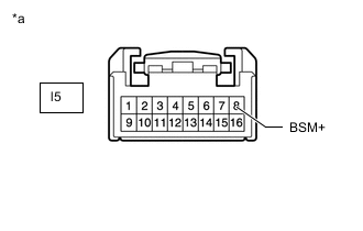
*a Front view of wire harness connector
(to Outer Rear View Mirror Assembly RH)
Disconnect the outer rear view mirror assembly RH connector.
-
Disconnect the IND2 outer rear view mirror RH connector.
-
Measure the resistance according to the value(s) in the table below.
Standard Resistance Tester Connection Condition Specified Condition l5-8 (BSM+) - Body ground Always 10 kΩ or higher Result Proceed to OK NG
NG
REPLACE OUTER REAR VIEW MIRROR ASSEMBLY RH Click here
OK
-
-
CHECK OUTER MIRROR CONTROL ECU ASSEMBLY RH
-
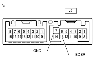
*a Component without harness connected
(Outer Mirror Control ECU Assembly RH)
Disconnect the outer mirror control ECU assembly RH connector.
-
Measure the resistance according to the value(s) in the table below.
Standard Resistance Tester Connection Condition Specified Condition L5-13 (BDSR) - L5-7 (GND) Always 10 kΩ or higher Result Proceed to OK NG
NG
REPLACE OUTER MIRROR CONTROL ECU ASSEMBLY RH Click here
OK
-
-
CHECK OUTER REAR VIEW MIRROR RH
-
Replace the outer rear view mirror RH.
-
Clear the DTCs.
Body Electrical > Blind Spot Monitor Slave > Clear DTCs -
Recheck for DTCs and check if the same DTC is output again.
Body Electrical > Blind Spot Monitor Slave > Trouble CodesOK DTC C1AB3 is not output. Result Proceed to OK NG
OK
END (OUTER REAR VIEW MIRROR RH WAS DEFECTIVE)
NG
REPLACE BLIND SPOT MONITOR SENSOR RH Click here
-