ENGINE SWITCH INSPECTION
PROCEDURE
INSPECT ENGINE SWITCH
Measure the resistance according to the value(s) in the table below.
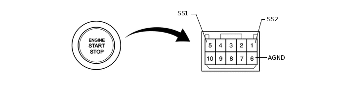
Standard Resistance
Tester Connection
Switch Condition
Specified Condition
5 (SS1) - 6 (AGND)
Not pushed
10 kΩ or higher
1 (SS2) - 6 (AGND)
5 (SS1) - 6 (AGND)
Pushed
Below 1 Ω
1 (SS2) - 6 (AGND)
If the result is not as specified, replace the engine switch.
Apply battery voltage between the terminals of the switch, and check the illumination condition of the engine switch.
Note:If the positive (+) lead and the negative (-) lead are incorrectly connected, the engine switch indicator light will not illuminate.
If the voltage is too low, the indicator light will not illuminate.
OK
Measurement Condition
Specified Condition
Battery positive (+) → Terminal 9 (SWIL)
Battery negative (-) → Terminal 6 (AGND)
Illuminates
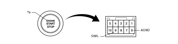
*a
Indicator Light
-
-
If the result is not as specified, replace the engine switch.