MULTI-DISPLAY INSTALLATION
CAUTION / NOTICE / HINT
Tech Tips
-
Use the same procedure for RHD and LHD vehicles.
-
The procedure listed below is for LHD vehicles.
PROCEDURE
-
INSTALL MULTI-DISPLAY ASSEMBLY
-
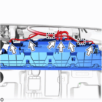
Connect each connectors and attach the clamp.
-
Move the multi-display assembly as shown in the illustration
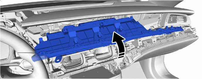

Install in this Direction - - -
Attach the clip to install the multi-display assembly.
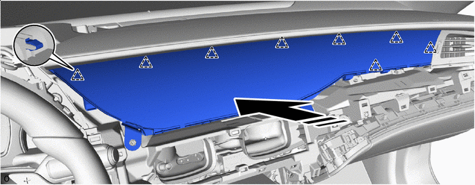
Install in this Direction - - Note
Do not subject the multi-display assembly to excessive force or damage it.
-
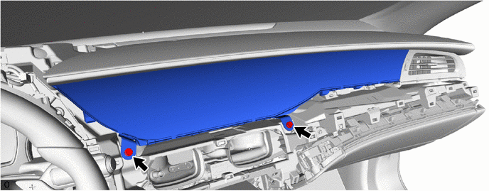
Install the 2 bolts.
-
-
INSTALL INSTRUMENT CLUSTER FINISH PANEL GARNISH ASSEMBLY
-
INSTALL INSTRUMENT PANEL SAFETY PAD INSERT SUB-ASSEMBLY
-
INSTALL NO. 2 INSTRUMENT PANEL SAFETY PAD SUB-ASSEMBLY
-
INSTALL LOWER INSTRUMENT PANEL FINISH PANEL ASSEMBLY
-
INSTALL LOWER NO. 1 INSTRUMENT PANEL PAD SUB-ASSEMBLY
-
INSTALL INSTRUMENT SIDE PANEL RH
-
INSTALL INSTRUMENT SIDE PANEL LH
-
CONNECT CABLE TO NEGATIVE BATTERY TERMINAL
-
for 8GR-FKS:
-
for V35A-FTS:
Note
When disconnecting the cable, some systems need to be initialized after the cable is reconnected.
-
-
INSTALL LUGGAGE COMPARTMENT MAT SUB-ASSEMBLY
-
PERFORM DIAGNOSTIC SYSTEM CHECK
-
INSPECT SRS WARNING LIGHT