FRONT DRIVE SHAFT ASSEMBLY REASSEMBLY
PROCEDURE
INSTALL FRONT DRIVE SHAFT DUST COVER

Using SST and a press, install a new dust cover.
09527-10011
INSTALL SHAFT SNAP RING

Install a new shaft snap ring.
INSTALL OUTBOARD JOINT BOOT

*1
Vinyl Tape
Tip:Before installing the boot, wrap vinyl tape around the spline of the shaft to prevent damage to the boot.
Temporarily install a new outboard joint boot with 2 new clamps to the outboard joint.
Pack the outboard joint and boot with grease from the boot kit.
Standard grease capacity
266 to 276 g (9.4 to 9.7 oz.)
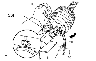
INSTALL FRONT NO. 2 AXLE OUTBOARD JOINT BOOT CLAMP
Hold the drive shaft lightly in a vise between aluminum plates.
Note:Do not overtighten the vise.
-

*a
Hold
*b
Turn
Place SST onto the front No. 2 axle outboard joint boot clamp.
09521-24010
Tighten SST so that the No. 2 front axle outboard joint boot clamp is pinched.
Note:Do not overtighten SST.
-

Using SST, measure the clearance of the No. 2 front axle out board joint boot clamp.
09240-00020
Standard clearance
2.1 mm (0.0827 in.) or less
Note:If the measured value is more than the specified value, retighten the clamp.
INSTALL FRONT NO. 1 AXLE OUTBOARD JOINT BOOT CLAMP
Hold the drive shaft lightly in a vise between aluminum plates.
Note:Do not overtighten the vise.
Secure the outboard joint boot clamp to the boot.
-
*a
Hold
*b
Turn
Place SST onto the outboard joint boot clamp.
09521-24010
Tighten SST so that the front axle outboard joint boot clamp is pinched.
Note:Do not overtighten SST.
-

Using SST, measure the clearance of the front axle outboard joint boot clamp.
09240-00020
Standard clearance
1.3 mm (0.0512 in.) or less
Note:If the measured value is more than the specified value, retighten the clamp.
INSTALL INBOARD JOINT BOOT
Temporarily install a new inboard joint boot to the outboard joint.
INSTALL FRONT AXLE INBOARD JOINT ASSEMBLY
Install new parts to the outboard joint in the following order.
1.
Front axle inboard joint boot clamp
2.
Front axle inboard joint boot
3.
Front No. 2 axle inboard joint boot clamp
Secure the outboard joint shaft in a vise between aluminum plates.
Note:Do not overtighten the vise.
-

*1
Matchmark
*a
Beveled Side
Align the matchmarks and install the tripod joint to the outboard joint.
Note:Position tripod so that the beveled side of the tripod faces toward the inboard joint.
Align the matchmarks and install the tripod to the inboard joint.
Using a brass bar and hammer, tap the tripod onto the outboard joint.
Note:Do not hit the roller portion.
Keep the tripod joint free of foreign matter.
-

Using a snap ring expander, install a new snap ring.
Pack the inboard joint assembly and boot with grease from the boot kit.
Standard grease capacity
239 to 249 g (8.4 to 8.8 oz.)
-

*1
Matchmark
Align the matchmarks and install the inboard joint onto the outboard joint.
INSTALL FRONT NO. 1 AXLE INBOARD JOINT BOOT CLAMP
Hold the drive shaft lightly in a vise between aluminum plates.
Note:Do not overtighten the vise.
Secure the inboard joint boot clamp to the boot.
-

*a
Hold
*b
Turn
Place SST onto the inboard joint boot clamp.
09521-24010
Tighten SST so that the front axle inboard joint boot clamp is pinched.
Note:Do not overtighten SST.
-

Using SST, measure the clearance of the front axle inboard joint boot clamp.
09240-00020
Standard clearance
1.3 mm (0.0512 in.) or less
Note:If the measured value is more than the specified value, retighten the clamp.
INSTALL FRONT NO. 2 AXLE INBOARD JOINT BOOT CLAMP
Hold the inboard joint shaft assembly in a vise between aluminum plates.
Note:Do not overtighten the vise.
-

*a
Hold
*b
Turn
Place SST onto the No. 2 front axle inboard joint boot clamp.
09521-24010
Tighten SST so that the No. 2 front axle inboard joint boot clamp is pinched.
Note:Do not overtighten SST.
-

Using SST, measure the clearance of the No. 2 front axle inboard joint boot clamp.
09240-00020
Standard clearance
2.1 mm (0.0827 in.) or less
Note:If the measured value is more than the specified value, retighten the clamp.