REAR DRIVE SHAFT ASSEMBLY REMOVAL
CAUTION / NOTICE / HINT
Use the same procedure for the RH and LH sides.
The procedure listed below is for the LH side.
PROCEDURE
REMOVE REAR WHEEL
REMOVE REAR AXLE SHAFT NUT LH
DISCONNECT REAR SPEED SENSOR LH
DISCONNECT DIFFERENTIAL CARRIER ASSEMBLY
REMOVE REAR DRIVE SHAFT ASSEMBLY LH
-
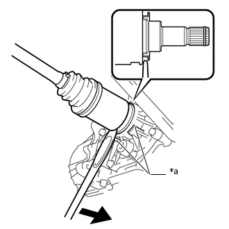
*a
Rib
With ribs:
Set the tip of the tire lever to the position on the rear drive shaft inboard joint assembly LH shown in the illustration. Then, using the ribbed part of the rear differential carrier assembly as a fulcrum, disconnect the rear drive shaft assembly LH.
Note:Do not scratch the rear drive shaft dust cover.
-
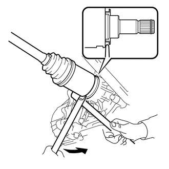
Without ribs:
Set the tip of a wheel nut wrench to the position on the rear drive shaft inboard joint assembly LH shown in the illustration. Then, using a brass bar as a fulcrum, disconnect the rear drive shaft assembly LH.
Note:Do not scratch the rear drive shaft dust cover.
-
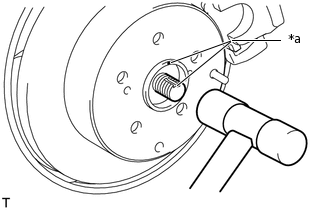
*a
Matchmark
Put matchmarks on the rear drive shaft assembly LH and rear axle hub assembly.
Note:Do not use a punch to make the matchmarks.
Using a plastic-faced hammer, remove the rear drive shaft assembly LH from the rear axle hub assembly.
Note:Be careful not to damage the boot, dust cover and speed sensor rotor.
Do not excessively push out the rear drive shaft assembly LH from the rear axle hub assembly.
-
REMOVE REAR DRIVE SHAFT INBOARD JOINT SHAFT SNAP RING LH
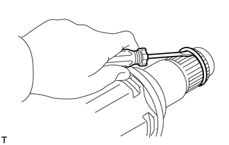
Using a screwdriver, remove the rear drive shaft inboard joint shaft snap ring LH.