POWER WINDOW CONTROL SYSTEM TERMINALS OF ECU
-
CHECK MULTIPLEX NETWORK MASTER SWITCH ASSEMBLY
-
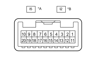
*A for LHD *B for RHD Disconnect the I5*1 or I2*2 multiplex network master switch assembly connector.
-
*1: for LHD
-
*2: for RHD
-
-
Measure the voltage and resistance according to the value(s) in the table below.
Tech Tips
Measure the values on the wire harness side with the connector disconnected.
for LHD Terminal No. (Symbol) Wiring Color Terminal Description Condition Specified Condition I5-11 (B) - I5-12 (GND) LA-GR - LA-R Power supply Always 11 to 14 V I5-12 (GND) - Body ground LA-R - Body ground Ground Always Below 1 Ω for RHD Terminal No. (Symbol) Wiring Color Terminal Description Condition Specified Condition I2-11 (B) - I2-12 (GND) LA-GR - LA-R Power supply Always 11 to 14 V I2-12 (GND) - Body ground LA-R - Body ground Ground Always Below 1 Ω -
Reconnect the I5*1 or I2*2 multiplex network master switch assembly connector.
-
*1: for LHD
-
*2: for RHD
-
-
Measure the voltage according to the value(s) in the table below.
for LHD Terminal No. (Symbol) Wiring Color Terminal Description Condition Specified Condition I5-15 (DOWN) - I5-12 (GND) G - LA-R Power window motor DOWN output Engine switch on (IG), driver door power window regulator switch not pushed or pulled 11 to 14 V Engine switch on (IG), driver door power window moving, driver door power window regulator switch pushed halfway down (Manual operation) Below 1 V I5-20 (UP) - I5-12 (GND) R - LA-R Power window motor UP output Engine switch on (IG), driver door power window regulator switch not pushed or pulled 11 to 14 V Engine switch on (IG), driver door power window moving, driver door power window regulator switch pulled halfway up (Manual operation) Below 1 V for RHD Terminal No. (Symbol) Wiring Color Terminal Description Condition Specified Condition I2-15 (DOWN) - I2-12 (GND) G - LA-R Power window motor DOWN output Engine switch on (IG), driver door power window regulator switch not pushed or pulled 11 to 14 V Engine switch on (IG), driver door power window moving, driver door power window regulator switch pushed halfway down (Manual operation) Below 1 V I2-20 (UP) - I2-12 (GND) R - LA-R Power window motor UP output Engine switch on (IG), driver door power window regulator switch not pushed or pulled 11 to 14 V Engine switch on (IG), driver door power window moving, driver door power window regulator switch pulled halfway up (Manual operation) Below 1 V -
Measure the pulse according to the value(s) in the table below.
for LHD Terminal No. (Symbol) Wiring Color Terminal Description Condition Specified Condition I5-17 (LIN1) - Body ground SB - Body ground LIN communication line Engine switch on (IG) Pulse generation for RHD Terminal No. (Symbol) Wiring Color Terminal Description Condition Specified Condition I2-17 (LIN1) - Body ground SB - Body ground LIN communication line Engine switch on (IG) Pulse generation
-
-
CHECK FRONT POWER WINDOW REGULATOR MOTOR ASSEMBLY LH (for LHD)
-
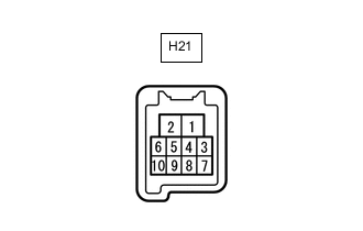
Disconnect the H21 front power window regulator motor assembly LH connector.
-
Measure the voltage and resistance according to the value(s) in the table below.
Tech Tips
Measure the values on the wire harness side with the connector disconnected.
Terminal No. (Symbol) Wiring Color Terminal Description Condition Specified Condition H21-1 (GND) - Body ground LA-B - Body ground Ground Always Below 1 Ω H21-2 (B) - Body ground LA-L - Body ground Power supply Always 11 to 14 V -
Reconnect the H21 front power window regulator motor assembly LH connector.
-
Measure the voltage according to the value(s) in the table below.
Terminal No. (Symbol) Wiring Color Terminal Description Condition Specified Condition H21-7 (DOWN) - H21-1 (GND) G - LA-B Power window motor DOWN input Engine switch on (IG), multiplex network master switch assembly (driver door power window regulator switch) not pushed or pulled 11 to 14 V Engine switch on (IG), driver door power window moving, multiplex network master switch assembly (driver door power window regulator switch) pushed halfway down (Manual operation) Below 1 V Engine switch on (IG), driver door power window fully closed 11 to 14 V Engine switch on (IG), driver door power window moving, multiplex network master switch assembly (driver door power window regulator switch) fully pushed down (Auto operation) Below 1 V Engine switch on (IG), driver door power window fully open 11 to 14 V H21-10 (UP) - H21-1 (GND) R - LA-B Power window motor UP input Engine switch on (IG), multiplex network master switch assembly (driver door power window regulator switch) not pushed or pulled 11 to 14 V Engine switch on (IG), driver door power window moving, multiplex network master switch assembly (driver door power window regulator switch) pulled halfway up (Manual operation) Below 1 V Engine switch on (IG), driver door power window fully opened 11 to 14 V Engine switch on (IG), driver door power window moving, multiplex network master switch assembly (driver door power window regulator switch) fully pulled up (Auto operation) Below 1 V Engine switch on (IG), driver door power window fully closed 11 to 14 V -
Measure the pulse according to the value(s) in the table below.
Terminal No. (Symbol) Wiring Color Terminal Description Condition Specified Condition H21-9 (LIN) - Body ground W - Body ground LIN communication line Engine switch on (IG) Pulse generation
-
-
CHECK FRONT POWER WINDOW REGULATOR MOTOR ASSEMBLY LH (for RHD)
-
Disconnect the H21 front power window regulator motor assembly LH connector.
-
Measure the voltage and resistance according to the value(s) in the table below.
Tech Tips
Measure the values on the wire harness side with the connector disconnected.
Terminal No. (Symbol) Wiring Color Terminal Description Condition Specified Condition H21-1 (GND) - Body ground LA-B - Body ground Ground Always Below 1 Ω H21-2 (B) - Body ground LA-R - Body ground Power supply Always 11 to 14 V -
Reconnect the H21 front power window regulator motor assembly LH connector.
-
Measure the voltage according to the value(s) in the table below.
Terminal No. (Symbol) Wiring Color Terminal Description Condition Specified Condition H21-7 (DOWN) - H21-1 (GND) G - LA-B Power window motor DOWN input Engine switch on (IG), power window regulator switch assembly not pushed or pulled 11 to 14 V Engine switch on (IG), front passenger door power window moving, power window regulator switch assembly pushed halfway down (Manual operation) Below 1 V Engine switch on (IG), front passenger door power window fully closed 11 to 14 V Engine switch on (IG), front passenger door power window moving, power window regulator switch assembly fully pushed down (Auto operation) Below 1 V Engine switch on (IG), front passenger door power window fully open 11 to 14 V H21-10 (UP) - H21-1 (GND) R - LA-B Power window motor UP input Engine switch on (IG), power window regulator switch assembly not pushed or pulled 11 to 14 V Engine switch on (IG), front passenger door power window moving, power window regulator switch assembly pulled halfway up (Manual operation) Below 1 V Engine switch on (IG), front passenger door power window fully open 11 to 14 V Engine switch on (IG), front passenger door power window moving, power window regulator switch assembly fully pulled up (Auto operation) Below 1 V Engine switch on (IG), front passenger door power window fully closed 11 to 14 V -
Measure the pulse according to the value(s) in the table below.
Terminal No. (Symbol) Wiring Color Terminal Description Condition Specified Condition H21-9 (LIN) - Body ground W - Body ground LIN communication line Engine switch on (IG) Pulse generation
-
-
CHECK FRONT POWER WINDOW REGULATOR MOTOR ASSEMBLY RH (for LHD)
-

Disconnect the H2 front power window regulator motor assembly RH connector.
-
Measure the voltage and resistance according to the value(s) in the table below.
Tech Tips
Measure the values on the wire harness side with the connector disconnected.
Terminal No. (Symbol) Wiring Color Terminal Description Condition Specified Condition H2-1 (GND) - Body ground LA-B - Body ground Ground Always Below 1 Ω H2-2 (B) - Body ground LA-R - Body ground Power supply Always 11 to 14 V -
Reconnect the H2 front power window regulator motor assembly RH connector.
-
Measure the voltage according to the value(s) in the table below.
Terminal No. (Symbol) Wiring Color Terminal Description Condition Specified Condition H2-4 (AUTO) - H2-1 (GND) B - LA-B Power window motor AUTO UP input Engine switch on (IG), front passenger door power window fully open 11 to 14 V Engine switch on (IG), front passenger door power window moving, power window regulator switch assembly fully pulled up (Auto operation) Below 1 V Engine switch on (IG), front passenger door power window fully closed 11 to 14 V Power window motor AUTO DOWN input Engine switch on (IG), front passenger door power window fully closed 11 to 14 V Engine switch on (IG), front passenger door power window moving, power window regulator switch assembly fully pushed down (Auto operation) Below 1 V Engine switch on (IG), front passenger door power window fully open 11 to 14 V H2-7 (DOWN) - H2-1 (GND) G - LA-B Power window motor DOWN input Engine switch on (IG), power window regulator switch assembly not pushed or pulled 11 to 14 V Engine switch on (IG), front passenger door power window moving, power window regulator switch assembly pushed halfway down (Manual operation) Below 1 V Engine switch on (IG), front passenger door power window fully closed 11 to 14 V Engine switch on (IG), front passenger door power window moving, power window regulator switch assembly fully pushed down (Auto operation) Below 1 V Engine switch on (IG), front passenger door power window fully open 11 to 14 V H2-10 (UP) - H2-1 (GND) R - LA-B Power window motor UP input Engine switch on (IG), power window regulator switch assembly not pushed or pulled 11 to 14 V Engine switch on (IG), front passenger door power window moving, power window regulator switch assembly pulled halfway up (Manual operation) Below 1 V Engine switch on (IG), front passenger door power window fully open 11 to 14 V Engine switch on (IG), front passenger door power window moving, power window regulator switch assembly fully pulled up (Auto operation) Below 1 V Engine switch on (IG), front passenger door power window fully closed 11 to 14 V -
Measure the pulse according to the value(s) in the table below.
Terminal No. (Symbol) Wiring Color Terminal Description Condition Specified Condition H2-9 (LIN) - Body ground W - Body ground LIN communication line Engine switch on (IG) Pulse generation
-
-
CHECK FRONT POWER WINDOW REGULATOR MOTOR ASSEMBLY RH (for RHD)
-
Disconnect the H2 front power window regulator motor assembly RH connector.
-
Measure the voltage and resistance according to the value(s) in the table below.
Tech Tips
Measure the values on the wire harness side with the connector disconnected.
Terminal No. (Symbol) Wiring Color Terminal Description Condition Specified Condition H2-1 (GND) - Body ground LA-B - Body ground Ground Always Below 1 Ω H2-2 (B) - Body ground LA-L - Body ground Power supply Always 11 to 14 V -
Reconnect the H2 front power window regulator motor assembly RH connector.
-
Measure the voltage according to the value(s) in the table below.
Terminal No. (Symbol) Wiring Color Terminal Description Condition Specified Condition H2-7 (DOWN) - H2-1 (GND) G - LA-B Power window motor DOWN input Engine switch on (IG), multiplex network master switch assembly (driver door power window regulator switch) not pushed or pulled 11 to 14 V Engine switch on (IG), driver door power window moving, multiplex network master switch assembly (driver door power window regulator switch) pushed halfway down (Manual operation) Below 1 V Engine switch on (IG), driver door power window fully closed 11 to 14 V Engine switch on (IG), driver door power window moving, multiplex network master switch assembly (driver door power window regulator switch) fully pushed down (Auto operation) Below 1 V Engine switch on (IG), driver door power window fully open 11 to 14 V H2-10 (UP) - H2-1 (GND) R - LA-B Power window motor UP input Engine switch on (IG), multiplex network master switch assembly (driver door power window regulator switch) not pushed or pulled 11 to 14 V Engine switch on (IG), driver door power window moving, multiplex network master switch assembly (driver door power window regulator switch) pulled halfway up (Manual operation) Below 1 V Engine switch on (IG), multiplex network master switch assembly (driver door power window regulator switch) fully open 11 to 14 V Engine switch on (IG), driver door power window moving, multiplex network master switch assembly (driver door power window regulator switch) fully pulled up (Auto operation) Below 1 V Engine switch on (IG), driver door power window fully closed 11 to 14 V -
Measure the pulse according to the value(s) in the table below.
Terminal No. (Symbol) Wiring Color Terminal Description Condition Specified Condition H2-9 (LIN) - Body ground W - Body ground LIN communication line Engine switch on (IG) Pulse generation
-
-
CHECK REAR POWER WINDOW REGULATOR MOTOR ASSEMBLY LH
-

Disconnect the K15 rear power window regulator motor assembly LH connector.
-
Measure the voltage and resistance according to the value(s) in the table below.
Tech Tips
Measure the values on the wire harness side with the connector disconnected.
Terminal No. (Symbol) Wiring Color Terminal Description Condition Specified Condition K15-1 (GND) - Body ground LA-B - Body ground Ground Always Below 1 Ω K15-2 (B) - Body ground LA-B - Body ground Power supply Always 11 to 14 V -
Reconnect the K15 rear power window regulator motor assembly LH connector.
-
Measure the voltage according to the value(s) in the table below.
Tester Connection Wiring Color Terminal Description Condition Specified Condition K15-4 (AUTO) - K15-1 (GND) GR - LA-B Power window motor AUTO UP input Engine switch on (IG), rear LH door power window fully open 11 to 14 V Engine switch on (IG), rear LH door power window moving, rear power window regulator switch assembly (for rear LH door) fully pulled up (Auto operation) Below 1 V Engine switch on (IG), rear LH door power window fully closed 11 to 14 V Power window motor AUTO DOWN input Engine switch on (IG), rear LH door power window fully closed 11 to 14 V Engine switch on (IG), rear LH door power window moving, rear power window regulator switch assembly (for rear LH door) fully pushed down (Auto operation) Below 1 V Engine switch on (IG), rear LH door power window fully open 11 to 14 V K15-7 (DOWN) - K15-1 (GND) LA-Y - LA-B Power window motor DOWN input Engine switch on (IG), rear power window regulator switch assembly (for rear LH door) not pushed or pulled 11 to 14 V Engine switch on (IG), rear LH door power window moving, rear power window regulator switch assembly (for rear LH door) pushed halfway down (Manual operation) Below 1 V Engine switch on (IG), rear LH door power window fully closed 11 to 14 V Engine switch on (IG), rear LH door power window moving, rear power window regulator switch assembly (for rear LH door) fully pushed down (Auto operation) Below 1 V Engine switch on (IG), rear LH door power window fully open 11 to 14 V K15-10 (UP) - K15-1 (GND) LA-BR - LA-B Power window motor UP input Engine switch on (IG), rear power window regulator switch assembly (for rear LH door) not pushed or pulled 11 to 14 V Engine switch on (IG), rear LH door power window moving, rear power window regulator switch assembly (for rear LH door) pulled halfway up (Manual operation) Below 1 V Engine switch on (IG), rear LH door power window fully open 11 to 14 V Engine switch on (IG), rear LH door power window moving, rear power window regulator switch assembly (for rear LH door) fully pulled up (Auto operation) Below 1 V Engine switch on (IG), rear LH door power window fully closed 11 to 14 V -
Measure the pulse according to the value(s) in the table below.
Terminal No. (Symbol) Wiring Color Terminal Description Condition Specified Condition K15-9 (LIN) - Body ground L - Body ground LIN communication line Engine switch on (IG) Pulse generation
-
-
CHECK REAR POWER WINDOW REGULATOR MOTOR ASSEMBLY RH
-

Disconnect the K1 rear power window regulator motor assembly RH connector.
-
Measure the voltage and resistance according to the value(s) in the table below.
Tech Tips
Measure the values on the wire harness side with the connector disconnected.
Terminal No. (Symbol) Wiring Color Terminal Description Condition Specified Condition K1-1 (GND) - Body ground LA-B - Body ground Ground Always Below 1 Ω K1-2 (B) - Body ground LA-BE - Body ground Power supply Always 11 to 14 V -
Reconnect the K1 rear power window regulator motor assembly RH connector.
-
Measure the voltage according to the value(s) in the table below.
Terminal No. (Symbol) Wiring Color Terminal Description Condition Specified Condition K1-4 (AUTO) - K1-1 (GND) GR - LA-B Power window motor AUTO UP input Engine switch on (IG), front passenger door power window fully open 11 to 14 V Engine switch on (IG), front passenger door power window moving, power window regulator switch assembly fully pulled up (Auto operation) Below 1 V Engine switch on (IG), front passenger door power window fully closed 11 to 14 V Power window motor AUTO DOWN input Engine switch on (IG), front passenger door power window fully closed 11 to 14 V Engine switch on (IG), front passenger door power window moving, power window regulator switch assembly fully pushed down (Auto operation) Below 1 V Engine switch on (IG), front passenger door power window fully open 11 to 14 V K1-7 (DOWN) - K1-1 (GND) LA-Y - LA-B Power window motor DOWN input Engine switch on (IG), power window regulator switch assembly not pushed or pulled 11 to 14 V Engine switch on (IG), front passenger door power window moving, power window regulator switch assembly pushed halfway down (Manual operation) Below 1 V Engine switch on (IG), front passenger door power window fully closed 11 to 14 V Engine switch on (IG), front passenger door power window moving, power window regulator switch assembly fully pushed down (Auto operation) Below 1 V Engine switch on (IG), front passenger door power window fully open 11 to 14 V K1-10 (UP) - K1-1 (GND) LA-BR - LA-B Power window motor UP input Engine switch on (IG), power window regulator switch assembly not pushed or pulled 11 to 14 V Engine switch on (IG), front passenger door power window moving, power window regulator switch assembly pulled halfway up (Manual operation) Below 1 V Engine switch on (IG), front passenger door power window fully open 11 to 14 V Engine switch on (IG), front passenger door power window moving, power window regulator switch assembly fully pulled up (Auto operation) Below 1 V Engine switch on (IG), front passenger door power window fully closed 11 to 14 V -
Measure the pulse according to the value(s) in the table below.
Terminal No. (Symbol) Wiring Color Terminal Description Condition Specified Condition K1-9 (LIN) - Body ground L - Body ground LIN communication line Engine switch on (IG) Pulse generation
-
-
CHECK FRONT MULTIPLEX NETWORK DOOR ECU LH

-
Disconnect the H31 front multiplex network door ECU LH connector.
-
Measure the voltage and resistance according to the value(s) in the table below.
Terminal No. (Symbol) Wiring Color Terminal Description Condition Specified Condition H31-6 (BDR) - H31-1 (GND) R - W-B Power supply Always 11 to 14 V H31-3 (SIG) - H31-1 (GND) B - W-B IG power supply Engine switch on (IG) 11 to 14 V H31-4 (CPUB) - H31-1 (GND) L - W-B Power supply Always 11 to 14 V H31-1 (GND) - Body ground W-B - Body ground Ground Always Below 1 Ω -
Reconnect the H31 front multiplex network door ECU LH connector.
-
Measure the voltage and resistance according to the value(s) in the table below.
Terminal No. (Symbol) Wiring Color Terminal Description Condition Specified Condition H31-5 (BDRJ) - H31-1 (GND) LA-L - W-B*1
LA-R - W-B*2
Power window regulator motor power supply Always 11 to 14 V H31-2 (PWE) - Body ground LA-B - Body ground Ground Always Below 1 Ω H31-9 (SGND) - Body ground R - Body ground Ground Always Below 1 Ω *1: for LHD
*2: for RHD
-
Measure the pulse according to the value(s) in the table below.
Terminal No. (Symbol) Wiring Color Terminal Description Condition Specified Condition H31-11 (LIN1) - Body ground SB - Body ground*1
B - Body ground*2
LIN communication line Engine switch on (IG) Pulse generation H31-13 (LIN3) - Body ground W - Body ground LIN communication line Engine switch on (IG) Pulse generation *1: for LHD
*2: for RHD
-
-
CHECK FRONT MULTIPLEX NETWORK DOOR ECU RH

-
Disconnect the H12 front multiplex network door ECU RH connector.
-
Measure the voltage and resistance according to the value(s) in the table below.
Terminal No. (Symbol) Wiring Color Terminal Description Condition Specified Condition H12-6 (BDR) - H12-1 (GND) R - W-B Power supply Always 11 to 14 V H12-3 (SIG) - H12-1 (GND) B - W-B Engine switch power supply Engine switch on (IG) 11 to 14 V H12-4 (CPUB) - H12-1 (GND) L - W-B IG power supply Always 11 to 14 V H12-1 (GND) - Body ground W-B - Body ground Ground Always Below 1 Ω -
Reconnect the H12 front multiplex network door ECU RH connector.
-
Measure the voltage and resistance according to the value(s) in the table below.
Terminal No. (Symbol) Wiring Color Terminal Description Condition Specified Condition H12-5 (BDRJ) - H12-1 (GND) LA-R - W-B*1
LA-L - W-B*2
Power window regulator motor power supply Always 11 to 14 V H12-2 (PWE) - Body ground LA-B - Body ground Ground Always Below 1 Ω H12-9 (SGND) - Body ground R - Body ground Ground Always Below 1 Ω *1: for LHD
*2: for RHD
-
Measure the pulse according to the value(s) in the table below.
Terminal No. (Symbol) Wiring Color Terminal Description Condition Specified Condition H12-11 (LIN1) - Body ground B - Body ground*1
SB - Body ground*2
LIN communication line Engine switch on (IG) Pulse generation H13-12 (LIN3) - Body ground W - Body ground LIN communication line Engine switch on (IG) Pulse generation *1: for LHD
*2: for RHD
-
-
CHECK REAR MULTIPLEX NETWORK DOOR ECU LH

-
Disconnect the K21 rear multiplex network door ECU LH connector.
-
Measure the voltage and resistance according to the value(s) in the table below.
Terminal No. (Symbol) Wiring Color Terminal Description Condition Specified Condition K21-4 (BDR) - K21-1 (GND) L - LA Power supply Always 11 to 14 V K21-12 (SIG) - K21-1 (GND) B - LA IG power supply Engine switch on (IG) 11 to 14 V K21-11 (CPUB) - K21-1 (GND) L - LA Power supply Always 11 to 14 V K21-1 (GND) - Body ground LA - Body ground Ground Always Below 1 Ω -
Reconnect the K21 rear multiplex network door ECU LH connector.
-
Measure the voltage and resistance according to the value(s) in the table below.
Terminal No. (Symbol) Wiring Color Terminal Description Condition Specified Condition K21-3 (BDRJ) - K21-1 (GND) LA-B - LA Power window regulator motor power supply Always 11 to 14 V K21-2 (PWE) - Body ground LA-B - Body ground Ground Always Below 1 Ω K21-9 (SGND) - Body ground R - Body ground Ground Always Below 1 Ω -
Measure the pulse according to the value(s) in the table below.
Terminal No. (Symbol) Wiring Color Terminal Description Condition Specified Condition K21-22 (LIN1) - Body ground B - Body ground LIN communication line Engine switch on (IG) Pulse generation K21-23 (LIN3) - Body ground L - Body ground LIN communication line Engine switch on (IG) Pulse generation
-
-
CHECK REAR MULTIPLEX NETWORK DOOR ECU RH

-
Disconnect the K7 rear multiplex network door ECU RH connector.
-
Measure the voltage and resistance according to the value(s) in the table below.
Terminal No. (Symbol) Wiring Color Terminal Description Condition Specified Condition K7-4 (BDR) - K7-1 (GND) B - LA Power supply Always 11 to 14 V K7-12 (SIG) - K7-1 (GND) L - LA IG switch power supply Engine switch on (IG) 11 to 14 V K7-11 (CPUB) - K7-1 (GND) L - LA Battery power supply Always 11 to 14 V K7-1 (GND) - Body ground LA - Body ground Ground Always Below 1 Ω -
Reconnect the K7 rear multiplex network door ECU RH connector.
-
Measure the voltage and resistance according to the value(s) in the table below.
Terminal No. (Symbol) Wiring Color Terminal Description Condition Specified Condition K7-3 (BDRJ) - K7-1 (GND) LA-BE - LA Power window regulator motor power supply Always 11 to 14 V K7-2 (PWE) - Body ground LA-B - Body ground Ground Always Below 1 Ω K7-9 (SGND) - Body ground R - Body ground Ground Always Below 1 Ω -
Measure the pulse according to the value(s) in the table below.
Terminal No. (Symbol) Wiring Color Terminal Description Condition Specified Condition K7-22 (LIN1) - Body ground B - Body ground LIN communication line Engine switch on (IG) Pulse generation K7-23 (LIN3) - Body ground L - Body ground LIN communication line Engine switch on (IG) Pulse generation
-
-
CHECK INSTRUMENT PANEL JUNCTION BLOCK ASSEMBLY AND MAIN BODY ECU (MULTIPLEX NETWORK BODY ECU)
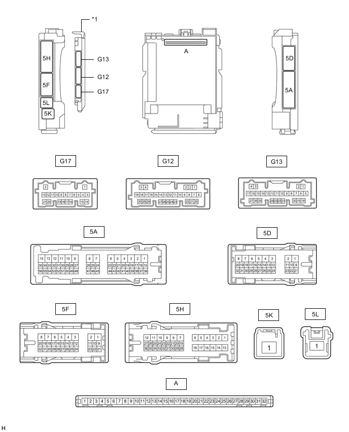
*1 Main Body ECU (Multiplex Network Body ECU) - -
-
Remove the main body ECU (multiplex network body ECU) from the instrument panel junction block assembly.
-
Reconnect the instrument panel junction block assembly connectors.
-
Measure the voltage and resistance according to the value(s) in the table below.
Terminal No. (Symbol) Wiring Color Terminal Description Condition Specified Condition A-11 (GND1) - Body ground None - Body ground Ground Always Below 1 Ω A-31 (BECU) - Body ground None - Body ground Battery power supply Always 11 to 14 V A-30 (ACC) - Body ground None - Body ground ACC power supply Engine switch on (ACC) 11 to 14 V Engine switch off Below 1 V A-32 (IG) - Body ground None - Body ground IG power supply Engine switch on (IG) 11 to 14 V Engine switch off Below 1 V -
Install the main body ECU (multiplex network body ECU) to the instrument panel junction block assembly.
-
Measure the voltage and waveform according to the value(s) in the table below.
for LHD Terminal No. (Symbol) Wiring Color Terminal Description Condition Specified Condition G12-1 (FLCY) - Body ground R - Body ground Front door courtesy light switch assembly LH input Front door courtesy light switch assembly LH open Below 1 V Front door courtesy light switch assembly LH closed 4.7 to 5.3 V G17-18 (L2) - Body ground Y - Body ground Driver door key-linked lock input Driver door key cylinder turned to lock Below 1 V Driver door key cylinder off Pulse generation G17-17 (UL3) - Body ground LG - Body ground Driver door key-linked unlock input Driver door key cylinder turned to unlock Below 1 V Driver door key cylinder off Pulse generation 5A-19 - Body ground L - Body ground LIN communication line Engine switch on (IG) Pulse generation 5H-34 - Body ground BE - Body ground LIN communication line Engine switch on (IG) Pulse generation 5H-35 - Body ground B - Body ground LIN communication line Engine switch on (IG) Pulse generation for RHD Terminal No. (Symbol) Wiring Color Terminal Description Condition Specified Condition G12-6 (FRCY) - Body ground R - Body ground Front door courtesy light switch assembly RH input Front door courtesy light switch assembly RH open Below 1 V Front door courtesy light switch assembly RH closed 4.7 to 5.3 V G17-18 (L2) - Body ground Y - Body ground Driver door key-linked lock input Driver door key cylinder turned to lock Below 1 V Driver door key cylinder off Pulse generation G17-17 (UL3) - Body ground LG - Body ground Driver door key-linked unlock input Driver door key cylinder turned to unlock Below 1 V Driver door key cylinder off Pulse generation 5A-40 - Body ground L - Body ground LIN communication line Engine switch on (IG) Pulse generation 5H-33 - Body ground LG - Body ground LIN communication line Engine switch on (IG) Pulse generation 5H-34 - Body ground B - Body ground LIN communication line Engine switch on (IG) Pulse generation
-