ELECTRIC PARKING BRAKE SYSTEM Electric Parking Brake AUTO Indicator Light Circuit
DESCRIPTION
Pulling the electric parking brake switch to the lock side for 5 seconds or more changes the AUTO function (shift-linked function) to ON, and an AUTO Mode ON message is displayed on the multi-information display in the combination meter. (for CVT)
Pressing the electric parking brake switch to the release side for 5 seconds or more changes the AUTO function (shift-linked function) to OFF, and an AUTO Mode OFF message is displayed on the multi-information display in the combination meter.(for CVT)
Pulling the electric parking brake switch to the lock side for 5 seconds or more changes the AUTO function (ignition switch-linked function) to ON, and the EPB-Auto OFF indicator light in the combination meter turns off. (for Manual Transaxle)
Pressing the electric parking brake switch to the release side for 5 seconds or more changes the AUTO function (ignition switch-linked function) to OFF, and the EPB-Auto OFF indicator light in the combination meter illuminates. (for Manual Transaxle)
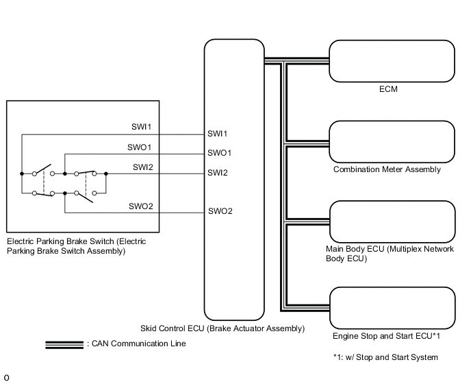
WIRING DIAGRAM
CAUTION / NOTICE / HINT
Note
-
Inspect the fuses for circuits related to this system before performing the following inspection procedure.
-
The electric parking brake may still operate up to 20 seconds after the ignition switch is turned off. Before disconnecting connectors or fuses, turn the ignition switch off and wait 20 seconds or more.
-
When replacing the skid control ECU (brake actuator assembly), operate the electric parking brake switch (electric parking brake switch assembly), as the parking brake indicator light (red) blinks when the ignition switch is first turned to ON.
PROCEDURE
-
CHECK CAN COMMUNICATION SYSTEM
-
Check if CAN communication system DTCs are output.
Result Result Proceed to DTCs are not output A DTCs are output B
B 
GO TO CAN COMMUNICATION SYSTEM Click here
A 
-
-
READ VALUE USING GTS (AUTO MODE)
-
Turn the ignition switch off.
-
Connect the GTS to the DLC3.
-
Turn the ignition switch to ON and the GTS on.
-
Enter the following menus: Chassis / Electric Parking Brake / Data List.
-
Check the values by referring to the table below.
Chassis > ABS/VSC/TRC/EPB > Data ListTester Display Measurement Item Range Normal Condition Diagnostic Note Auto Mode AUTO mode permission display OFF or ON OFF: Manual mode
ON: AUTO mode
-
Chassis > ABS/VSC/TRC/EPB > Data ListTester Display Auto Mode -
When switching the mode, check that the Data List display turns on and off.
Result Result Proceed to AUTO indicator light does not illuminate and turn off according to turning Active Test on and off A AUTO indicator light illuminates and turns off according to turning Active Test on and off B
B 
GO TO STEP 6 Click here
A
-
-
CHECK DTC
-
Check for DTCs.
Chassis > ABS/VSC/TRC/EPB > Trouble CodesResult Result Proceed to DTC is not output A DTC is output B
B
GO TO DIAGNOSTIC TROUBLE CODE CHART Click here
A
-
-
INSPECT ELECTRIC PARKING BRAKE SWITCH (ELECTRIC PARKING BRAKE SWITCH ASSEMBLY)
-
Inspect the electric parking brake switch (electric parking brake switch assembly).
Result Proceed to OK NG
NG
REPLACE ELECTRIC PARKING BRAKE SWITCH (ELECTRIC PARKING BRAKE SWITCH ASSEMBLY) Click here
OK
-
-
CHECK HARNESS AND CONNECTOR (SKID CONTROL ECU (BRAKE ACTUATOR ASSEMBLY) - ELECTRIC PARKING BRAKE SWITCH (ELECTRIC PARKING BRAKE SWITCH ASSEMBLY))
-
Disconnect the F67 electric parking brake switch (electric parking brake switch assembly) connector.
-
Disconnect the A42 skid control ECU (brake actuator assembly) connector.
-
Measure the resistance according to the value(s) in the table below.
Standard Resistance Tester Connection Condition Specified Condition A42-31 (SWI1) - F67-6 (SWI1) Always Below 5 Ω A42-32 (SWO1) - F67-5 (SWO1) Always Below 5 Ω A42-15 (SWI2) - F67-4 (SWI2) Always Below 5 Ω A42-16 (SWO2) - F67-3 (SWO2) Always Below 5 Ω A42-31 (SWI1) or F67-6 (SWI1) - Body ground Always 10 kΩ or higher A42-32 (SWO1) or F67-5 (SWO1) - Body ground Always 10 kΩ or higher A42-15 (SWI2) or F67-4 (SWI2) - Body ground Always 10 kΩ or higher A42-16 (SWO2) or F67-3 (SWO2) - Body ground Always 10 kΩ or higher Result Proceed to OK NG
NG
REPAIR OR REPLACE HARNESS OR CONNECTOR
OK
-
-
PERFORM ACTIVE TEST USING GTS (AUTO MODE)
-
Turn the ignition switch off.
-
Connect the GTS to the DLC3.
-
Turn the ignition switch to ON.
-
Turn the GTS on.
-
Enter the following menus: Chassis / Electric Parking Brake / Data List.
-
Read the Data List according to the display on the GTS.
Chassis > ABS/VSC/TRC/EPB > Active TestTester Display Measurement Item Control Range Diagnostic Note Auto Mode AUTO mode ON or OFF
-
Vehicle stopped
-
Ignition switch ON
Chassis > ABS/VSC/TRC/EPB > Active TestTester Display Auto Mode -
-
Select the Data List on the GTS.
Chassis > ABS/VSC/TRC/EPB > Data ListTester Display Measurement Item Range Normal Condition Diagnostic Note Auto Mode AUTO mode permission display ON or OFF ON: AUTO mode
OFF: Manual mode
-
Chassis > ABS/VSC/TRC/EPB > Data ListTester Display Auto Mode -
Perform the Auto Mode Active Test, and check that the Data List display changes.
Result Result Proceed to Check the operating condition of the "Auto Mode" when operating it using the GTS. (for LHD) A Check the operating condition of the "Auto Mode" when operating it using the GTS. (for RHD) B "Auto Mode" in the Data List turns ON/OFF using the Active Test. C
A
REPLACE SKID CONTROL ECU (BRAKE ACTUATOR ASSEMBLY) Click here
B
REPLACE SKID CONTROL ECU (BRAKE ACTUATOR ASSEMBLY) Click here
C
-
-
INSPECT COMBINATION METER ASSEMBLY
-
Perform the Active Test of the combination meter assembly using the GTS. (for CVT)
Body Electrical > Combination Meter > Active TestTester Display Meter Display 1 -
Perform the Active Test of the combination meter assembly using the GTS. (for Manual Transaxle)
Body Electrical > Combination Meter > Active TestTester Display EPB Auto OFF Indicator -
Check the multi-information display the combination meter assembly turn ON or OFF in accordance with the GTS operation. (for CVT)
OK The message in the multi-information display appears and disappears in accordance with the Active Test operation. -
Check that the Auto off indicator light on the combination meter assembly turns ON or OFF in accordance with the GTS operation. (for Manual Transaxle)
OK The indicator light turns on and off in accordance with the Active Test operation. Result Result Proceed to OK (for LHD) A OK (for RHD) B NG C
A
REPLACE SKID CONTROL ECU (BRAKE ACTUATOR ASSEMBLY) Click here
B
REPLACE SKID CONTROL ECU (BRAKE ACTUATOR ASSEMBLY) Click here
C
GO TO METER / GAUGE SYSTEM Click here
-