HV BATTERY INSTALLATION
PROCEDURE
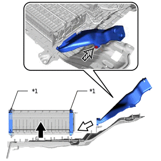
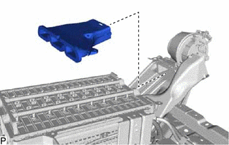
INSTALL NO. 2 HYBRID BATTERY EXHAUST DUCT
CAUTION:Wear insulated gloves and use insulated tools.
-
*1
Hybrid Battery End Plate

Raise Hybrid Battery Stack

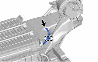
Install No. 2 Hybrid Battery Exhaust Duct

Secure Clip
Raise the hybrid battery stack vertically.
Note:Make sure to hold the hybrid battery stack by the hybrid battery end plates shown in the illustration.
Make sure to raise the hybrid battery stack as much as necessary for the removal of the No. 2 hybrid battery exhaust duct.
Make sure to raise the hybrid battery stack vertically.
Install the No. 2 hybrid battery exhaust duct to the HV battery, and secure it with the clip.
Install the hybrid battery stack with the 3 nuts.
7.5 N*m
76 kgf*cm
66 in.*lbf
-
INSTALL NO. 1 HYBRID BATTERY EXHAUST DUCT
CAUTION:Wear insulated gloves and use insulated tools.
-
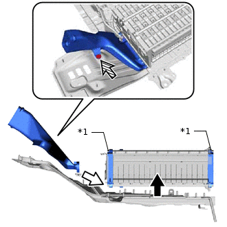
*1
Hybrid Battery End Plate
Raise Hybrid Battery Stack
Install No. 2 Hybrid Battery Exhaust Duct
Secure Clip
Raise the hybrid battery stack vertically.
Note:Make sure to hold the hybrid battery stack by the hybrid battery end plates shown in the illustration.
Make sure to raise the hybrid battery stack as much as necessary for the removal of the No. 1 hybrid battery exhaust duct.
Make sure to raise the hybrid battery stack vertically.
Install the No. 1 hybrid battery exhaust duct to the HV battery, and secure it with the clip.
Install the hybrid battery stack with the 3 nuts.
7.5 N*m
76 kgf*cm
66 in.*lbf
-
INSTALL NO. 2 HYBRID BATTERY COVER INTAKE DUCT
CAUTION:Wear insulated gloves and use insulated tools.
-
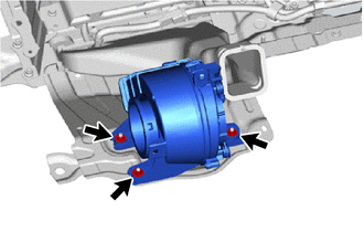
Install the battery cooling blower assembly LH with the 3 nuts.
7.5 N*m
76 kgf*cm
66 in.*lbf
-
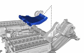
Install the No. 2 hybrid battery cover intake duct.
-
INSTALL NO. 1 HYBRID BATTERY COVER INTAKE DUCT
CAUTION:Wear insulated gloves and use insulated tools.
-
Install the battery cooling blower assembly RH with the 3 nuts.
7.5 N*m
76 kgf*cm
66 in.*lbf
-
Install the No. 1 hybrid battery cover intake duct.
-
Connect the intake temperature sensor and wire harness clamp.
-
INSTALL NO. 1 HYBRID BATTERY SHIELD SUB-ASSEMBLY
CAUTION:Wear insulated gloves and use insulated tools.
Install the No. 1 hybrid battery shield sub-assembly with the 2 nuts.
7.5 N*m
76 kgf*cm
66 in.*lbf
Connect the 4 wire harness clamps.
INSTALL NO. 1 HYBRID VEHICLE BATTERY CARRIER BRACKET SUB-ASSEMBLY
CAUTION:Wear insulated gloves and use insulated tools.
-
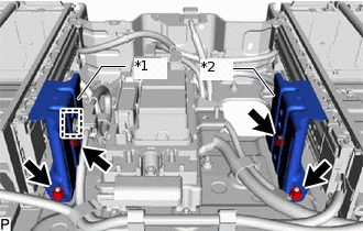
*1
No. 1 Hybrid Vehicle Battery Carrier Bracket Sub-assembly LH Side
*2
No. 1 Hybrid Vehicle Battery Carrier Bracket Sub-assembly RH Side
Install the No. 1 hybrid vehicle battery carrier bracket sub-assembly LH side with the 2 nuts.
7.5 N*m
76 kgf*cm
66 in.*lbf
Install the No. 1 hybrid vehicle battery carrier bracket sub-assembly RH side with the 2 nuts.
7.5 N*m
76 kgf*cm
66 in.*lbf
Connect the wire harness clamp to the No. 1 hybrid vehicle carrier bracket sub-assembly LH side.
-
INSTALL HYBRID BATTERY COVER SUB-ASSEMBLY LH
CAUTION:Wear insulated gloves and use insulated tools.
-
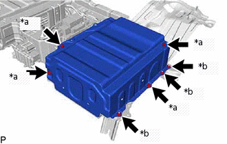
*a
Bolt
*b
Nut
Install the hybrid battery cover sub-assembly LH with the 4 bolts and 3 nuts.
7.5 N*m
76 kgf*cm
66 in.*lbf
-
INSTALL HYBRID BATTERY COVER SUB-ASSEMBLY RH
CAUTION:Wear insulated gloves and use insulated tools.
-
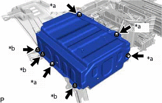
*a
Bolt
*b
Nut
Install the hybrid battery cover sub-assembly RH with the 4 bolts and 3 nuts.
7.5 N*m
76 kgf*cm
66 in.*lbf
-
INSTALL NO. 2 HYBRID BATTERY PACK WIRE
CAUTION:Wear insulated gloves.
Connect the 2 wire harness clamps and install the No. 2 hybrid battery pack wire.
INSTALL BATTERY VOLTAGE SENSOR
INSTALL LOWER NO. 2 HYBRID BATTERY CARRIER PATCH
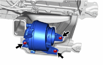
INSTALL HV BATTERY JUNCTION BLOCK ASSEMBLY
CAUTION:Wear insulated gloves and use insulated tools.
Install the hybrid battery junction block assembly with the 3 nuts.
7.5 N*m
76 kgf*cm
66 in.*lbf
-
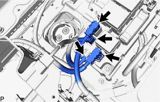
Connect the 4 connectors.
Note:Make sure that the connectors are securely attached.
INSTALL NO. 4 HYBRID BATTERY EXHAUST DUCT
Install the No. 4 hybrid battery exhaust duct to the No. 2 hybrid battery exhaust duct.
INSTALL NO. 3 HYBRID BATTERY EXHAUST DUCT
Install the No. 3 hybrid battery exhaust duct to the No. 1 hybrid battery exhaust duct.
INSTALL HV BATTERY ASSEMBLY
CAUTION:Wear insulated gloves and protective goggles.
Use cardboard or other similar material to protect the HV battery assembly and vehicle body from damage.
Install the HV battery assembly from the rear of the vehicle.
Note: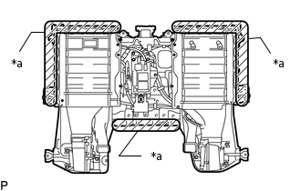
*a
Areas to be Held
Hold the areas shown in the illustration and lift up the HV battery assembly.
Since the HV battery assembly is very heavy, 4 people are needed to install the HV battery assembly. When removing the HV battery assembly, do not damage the parts around it.
To prevent the wire harness from being caught, make sure to bundle the wire harness using insulating tape or equivalent.
When removing/installing/moving the HV battery assembly, make sure not to tilt it more than 80°.
Tip:When removing and installing the HV battery, do so from the back door opening.
Lift up the HV battery assembly, and pull out the 3 cables from the HV battery assembly towards the lower side.
Note:To prevent the wire harness from being caught, make sure to bundle the wire harness using insulating tape or equivalent.
Since the HV battery assembly is very heavy, 4 people are needed to install the HV battery assembly. When removing the HV battery assembly, do not damage the parts around it.
-
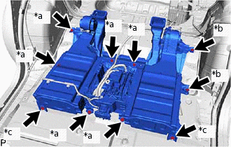
*a
Bolt
*b
Ground Bolt
*c
Nut
Install the HV battery assembly with the 6 bolts, 2 nuts and 2 ground bolts.
19 N*m
194 kgf*cm
14 ft.*lbf
-
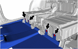
Connect the front floor carpet assembly with the 4 clips.
CONNECT WIRE HARNESS
CAUTION:Wear insulated gloves and use insulated tools.
Connect the connector and wire harness clamp to the battery cooling blower assembly LH.
Connect the connector and wire harness clamp to the battery cooling blower assembly RH.
Connect the 6 wire harness clamps and 2 connectors to the HV battery assembly.
-
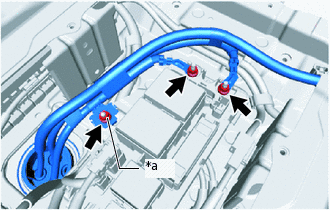
*a
Ground Terminal
Using an insulated tool wrapped with electrical tape, connect the 2 No. 5 floor wires (high-voltage cables) and ground terminal with the 3 nuts.
9.0 N*m
92 kgf*cm
80 in.*lbf
INSTALL AUXILIARY BATTERY
CAUTION:Wear insulated gloves.
Install the auxiliary battery.
-
Connect the 6 wire harness clamps and connector.
Connect the positive (+) auxiliary battery terminal.
6.5 N*m
66 kgf*cm
58 in.*lbf
HIGH VOLTAGE CABLE CONNECTION CONDITION
INSTALL NO. 2 HYBRID VEHICLE BATTERY SHIELD REINFORCEMENT
INSTALL NO. 1 EV BATTERY INTAKE DUCT
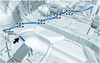
Install the No. 1 hybrid battery intake duct with the 2 clips.
INSTALL NO. 2 HYBRID BATTERY INTAKE DUCT
Install the No. 2 hybrid battery intake duct with the 2 clips.
INSTALL DECK TRIM SIDE PANEL ASSEMBLY LH
INSTALL DECK TRIM SIDE PANEL ASSEMBLY RH
INSTALL REAR FLOOR FINISH PLATE (w/o Full Size Spare Tire)
INSTALL REAR DECK TRIM COVER (w/ Full Size Spare Tire)
INSTALL REAR SEAT ASSEMBLY
INSTALL NO.1 INVERTER RESERVE TANK BRACKET (for 2WD)
CONNECT INVERTER RESERVE TANK ASSEMBLY
CONNECT WIRE HARNESS
INSTALL SERVICE PLUG GRIP
CONNECT CABLE TO NEGATIVE AUXILIARY BATTERY TERMINAL
Note:When disconnecting the cable, some systems need to be initialized after the cable is reconnected.