ENGINE UNIT REPLACEMENT
-
REMOVE TIMING CHAIN COVER OIL SEAL
-
Using a screwdriver, pry out the oil seal.
Note
Be careful not to damage the oil pump body. Tape the screwdriver before use..
-
-
INSTALL TIMING CHAIN COVER OIL SEAL
-
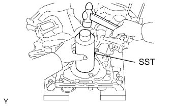
Using SST and a hammer, tap in a new oil seal until its surface is flush with the timing chain cover edge.
- SST
- 09226-10010
-
Apply MP grease to the oil seal lip.
-
-
REMOVE REAR ENGINE OIL SEAL
-
Using a screwdriver and hammer, tap out the oil seal.
-
-
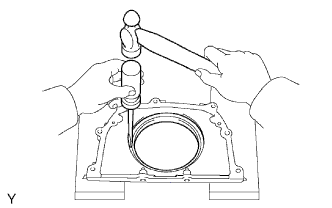
INSTALL REAR ENGINE OIL SEAL
-
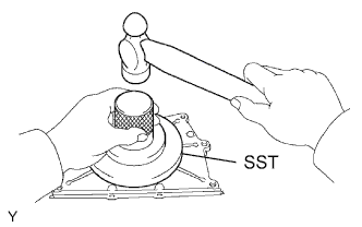
Using SST and a hammer, tap in a new oil seal until its surface is flush with the rear oil seal retainer edge.
- SST
- 09223-78010
-
Apply MP grease to the oil seal lip.
-
-
REMOVE VALVE GUIDE BUSH
-
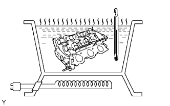
Gradually heat the cylinder head to 80 to 100°C (176 to 212°F).
-
Place the cylinder head on the wooden block.
-
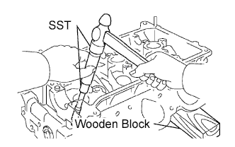
Using SST, tap out the valve guide bush.
- SST
- 09201-10000
- 09201-01055
- 09950-70010 ( 09951-07100 )
-
-
INSTALL VALVE GUIDE BUSH
-
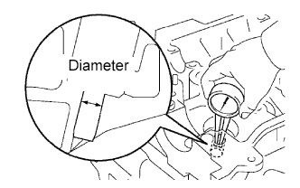
Using a caliper gauge, measure the bush bore diameter of the cylinder head.
Bush bore diameter 10.295 to 10.315 mm (0.4053 to 0.4061 in.) If the bush bore diameter of the cylinder head is greater than 10.315 mm (0.4061 in.), machine the bush bore to the dimension of 10.345 to 10.365 mm (0.4073 to 0.4081 in.).
Valve guide bush diameter Valve Specified Condition STD 10.333 to 10.344 mm (0.4068 to 0.4072 in.) O/S 0.05 10.383 to 10.394 mm (0.4088 to 0.4092 in.) -
Gradually heat the cylinder head to 80 to 100°C (176 to 212°F).
-
Place the cylinder head on the wooden block.
-
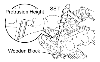
Using SST, tap in a new valve guide bush to the specified protrusion height.
- SST
- 09201-10000
- 09201-01055
- 09950-70010 ( 09951-07100 )
Protrusion height 9.3 to 9.7 mm (0.366 to 0.382 in.) -
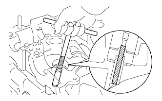
Using a sharp 5.5 mm reamer, ream the valve guide bush to obtain the standard specified clearance between the valve guide bush and valve stem.
Standard oil clearance Valve Specified Condition Intake 0.025 to 0.060 mm (0.0010 to 0.0024 in.) Exhaust 0.030 to 0.065 mm (0.0012 to 0.0026 in.)
-
-
REMOVE CONNECTING ROD SMALL END BUSH
-
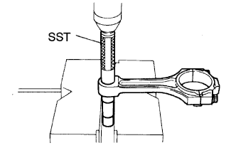
Using SST and a press, press out the bush.
- SST
- 09222-30010
-
-
INSTALL CONNECTING ROD SMALL END BUSH
-
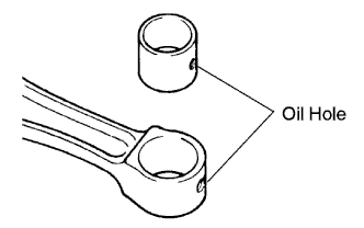
Align the oil holes of a new bush and the connecting rod.
-
Using SST and a press, press in the bush.
- SST
- 09222-30010
-
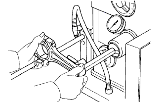
Using a pin hole grinder, hone the bush to obtain the standard specified clearance between the bush and piston pin.
Standard oil clearance 0.005 to 0.011 mm (0.0002 to 0.0004 in.) Tech Tips
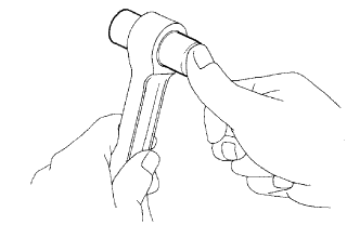
Check the piston pin fit at normal room temperature. Coat the piston pin with engine oil, and push it into the connecting rod with thumb.
-