COMBINATION SWITCH INSPECTION
PROCEDURE
-
INSPECT COMBINATION SWITCH ASSEMBLY
-
Inspect EV drive mode switch (combination switch assembly)
-
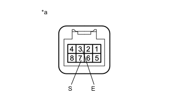
Text in Illustration *a Component without harness connected
(EV drive mode switch (combination switch assembly))
Measure the resistance according to the value(s) in the table below.
Standard Resistance Tester Connection Condition Specified Condition 7 (S) - 3 (E) EV drive mode switch (combination switch assembly) being pushed and held Below 1 Ω EV drive mode switch (combination switch assembly) not pushed 10 kΩ or higher If the result is not as specified, replace the combination switch assembly.
-
-
Inspect POWER mode switch (combination switch assembly)
-
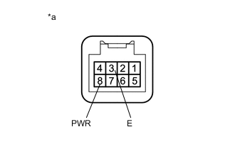
Text in Illustration *a Component without harness connected
(POWER mode switch (combination switch assembly))
Measure the resistance according to the value(s) in the table below.
Standard Resistance Tester Connection Condition Specified Condition 8 (PWR) - 3 (E) POWER mode switch (combination switch assembly) being pushed and held Below 1 Ω POWER mode switch (combination switch assembly) not pushed 10 kΩ or higher If the result is not as specified, replace the combination switch assembly.
-
-
Inspect ECO mode switch (combination switch assembly)
-
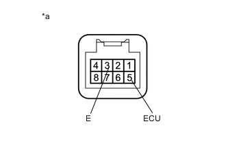
Text in Illustration *a Component without harness connected
(ECO mode switch (combination switch assembly))
Measure the resistance according to the value(s) in the table below.
Standard Resistance Tester Connection Condition Specified Condition 5 (ECU) - 3 (E) ECO mode switch (combination switch assembly) being pushed and held Below 1 Ω ECO mode switch (combination switch assembly) not pushed 10 kΩ or higher If the result is not as specified, replace the combination switch assembly.
-
-
Inspect illumination
-
Apply battery voltage between the terminals of the switch, and check the illumination condition of the combination switch assembly.

OK Measurement Condition Specified Condition Auxiliary battery positive (+) →Terminal 6 (ILL+)
Auxiliary battery negative (-) →Terminal 1 (ILL-)
Illuminates Text in Illustration *a Component without harness connected
(Combination Switch Assembly)
*b Combination switch assembly illumination If the result is not as specified, replace the combination switch assembly.
-
-