AUDIO AND VISUAL SYSTEM(w/ Multi-display) Mute Signal Circuit between Stereo Component Amplifier and Telematics Transceiver
| DTC Code | DTC Name |
|---|---|
| Mute Signal Circuit between Stereo Component Amplifier and Telematics Transceiver |
DESCRIPTION
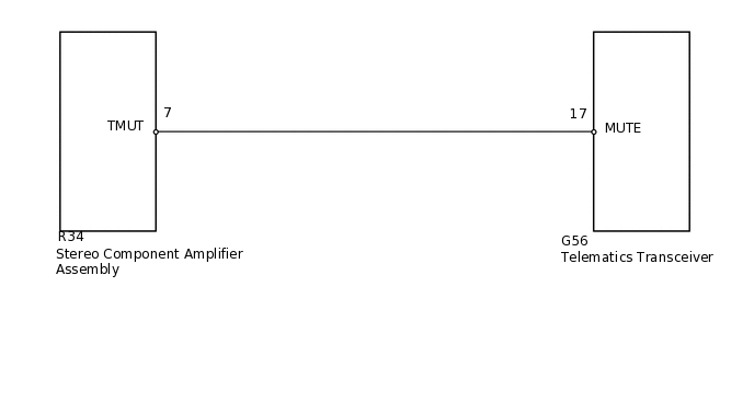
The telematics transceiver sends a mute signal to the stereo component amplifier assembly.
The stereo component amplifier assembly controls the volume according to the mute signal from the telematics transceiver.
WIRING DIAGRAM
PROCEDURE
INSPECT TELEMATICS TRANSCEIVER
-
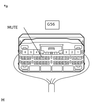
*a
Component with harness connected
(Telematics Transceiver)
Measure the voltage according to the value(s) in the table below.
Standard Voltage
Tester Connection
Condition
Specified Condition
G56-17 (MUTE) - Body ground
Engine switch on (ACC), audio system is playing → Emergency call mode
Higher than 3.5 V → Below 1 V
Result
Result
OK
NG
-
CHECK HARNESS AND CONNECTOR (STEREO COMPONENT AMPLIFIER - TELEMATICS TRANSCEIVER)
Disconnect the R34 stereo component amplifier assembly connector.
Disconnect the G56 telematics transceiver connector.
Measure the resistance according to the value(s) in the table below.
Standard Resistance
Tester Connection
Condition
Specified Condition
R34-7 (TMUT) - G56-17 (MUTE)
Always
Below 1 Ω
R34-7 (TMUT) - Body ground
Always
10 kΩ or higher
Result
Result
OK
NG
NG REPAIR OR REPLACE HARNESS OR CONNECTOR
INSPECT STEREO COMPONENT AMPLIFIER ASSEMBLY
-
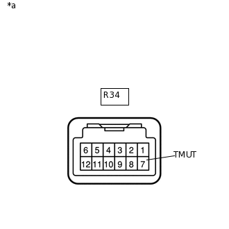
*a
Component without harness connected
(Stereo Component Amplifier Assembly)
Measure the voltage according to the value(s) in the table below.
Standard Voltage
Tester Connection
Switch Condition
Specified Condition
R34-7 (TMUT) - Body ground
Engine switch on (ACC)
Higher than 3.5 V
Result
Result
OK
NG
-