NAVIGATION SYSTEM(for DVD) Display Signal Circuit between Navigation ECU and Radio Receiver
| DTC Code | DTC Name |
|---|---|
| Display Signal Circuit between Navigation ECU and Radio Receiver |
DESCRIPTION
This circuit sends a DVD image signal from the radio receiver assembly to the display and navigation module display.
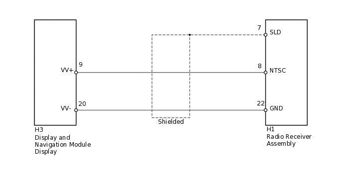
WIRING DIAGRAM
PROCEDURE
CHECK HARNESS AND CONNECTOR (RADIO RECEIVER - DISPLAY AND NAVIGATION MODULE DISPLAY)
Disconnect the H1 radio receiver assembly connector.
Disconnect the H3 display and navigation module display connector.
Measure the resistance according to the value(s) in the table below.
Standard Resistance
Tester Connection
Condition
Specified Condition
H1-8 (NTSC) - H3-9 (VV+)
Always
Below 1 Ω
H1-22 (GND) - H3-20 (VV-)
Always
Below 1 Ω
H1-8 (NTSC) - Body ground
Always
10 kΩ or higher
H1-22 (GND) - Body ground
Always
10 kΩ or higher
H1-7 (SLD) - Body ground
Always
10 kΩ or higher
Result
Result
OK
NG
NG REPAIR OR REPLACE HARNESS OR CONNECTOR
CHECK RADIO RECEIVER ASSEMBLY
-
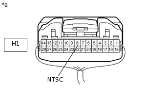
*a
Component with harness connected
(Radio Receiver Assembly)
Using an oscilloscope, check the waveform between each terminal and the body ground according to the conditions shown in the table below.
Standard
Tester Connection
Condition
Specified Condition
H1-8 (NTSC) - Body ground
Radio receiver is playing, image is being produced
Waveform synchronized with image is output
Result
Result
OK
NG
-