AIR CONDITIONING UNIT INSTALLATION
PROCEDURE
-
TEMPORARILY INSTALL AIR CONDITIONING UNIT ASSEMBLY
Note
-
Be sure to support the air conditioning unit assembly when installing it because failure to do so may cause brackets of the air conditioning unit assembly to break.
-
When installing the air conditioning unit, eliminate static electricity by touching the vehicle body to prevent the components from being damaged.
-
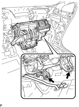
Temporarily install the air conditioning unit assembly with the bolt and nut.
-
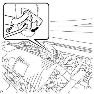
Connect the No. 1 cooler unit drain hose as shown in the illustration.
Note
Connect the No. 1 cooler unit drain hose firmly to prevent water leaks.
-
-
INSTALL INSTRUMENT PANEL REINFORCEMENT ASSEMBLY
-
Install the instrument panel reinforcement assembly with the 6 bolts <A>.
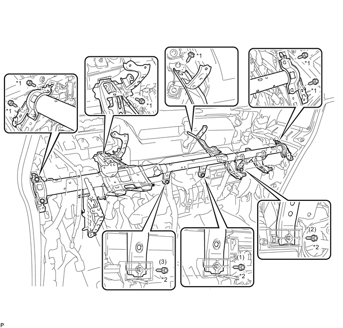
Text in Illustration *1 Bolt <A> *2 Bolt <B> - Torque:
- 29 N*m { 296 kgf*cm, 21 ft.*lbf }
-
Install the air conditioning unit assembly with the 3 bolts <B>.
Tech Tips
Tighten the bolts in the order shown in the illustration.
- Torque:
- 9.8 N*m { 100 kgf*cm, 87 in.*lbf }
-
Connect each connector.
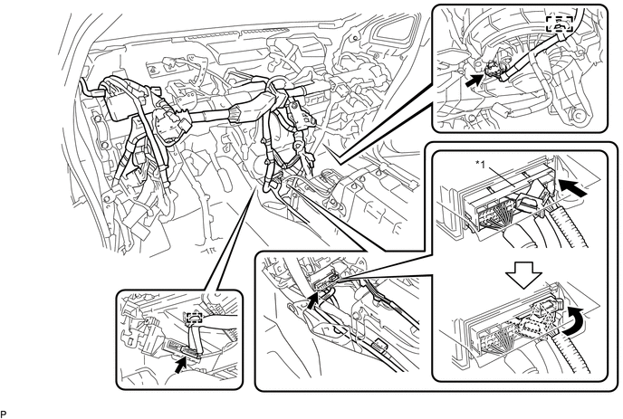
Text in Illustration *1 Center Airbag Sensor Connector - - -
Engage the 2 clamps.
-
Connect the center airbag sensor connector to the center airbag sensor assembly as shown in the illustration.
-
Check that there is no looseness in the installation parts of the center airbag sensor assembly.
-
Engage the 4 clamps.
-
Install the 2 bolts.
-
Install the bolt to connect the earth wire.
- Torque:
- 8.4 N*m { 86 kgf*cm, 74 in.*lbf }
-
Engage the 5 clamps.
-
Install the bolt.
-
-
INSTALL AIR CONDITIONING UNIT ASSEMBLY
-
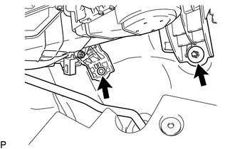
Install the air conditioning unit assembly with the bolt and nut.
- Torque:
- 9.8 N*m { 100 kgf*cm, 87 in.*lbf }
-
-
INSTALL REAR NO. 1 AIR DUCT
-
Engage the 8 claws to install the rear No. 1 air duct.
-
Engage the clamp.
-
-
INSTALL LOWER DEFROSTER NOZZLE ASSEMBLY
-
Engage the guide and 2 claws.
-
Install the lower defroster nozzle assembly with the 2 clips.
-
Engage the 2 clamps.
-
-
INSTALL NO. 2 INSTRUMENT PANEL BRACE SUB-ASSEMBLY
-
Install the No. 2 instrument panel brace sub-assembly with the screw and nut.
- Torque:
- Screw
- 4.0 N*m { 41 kgf*cm, 35 in.*lbf }
-
Engage the 3 clamps.
-
Install the bolt to connect the earth wire.
- Torque:
- 8.4 N*m { 86 kgf*cm, 74 in.*lbf }
-
Engage the 3 clamps.
-
Install the 2 bolts.
-
Engage the clamp.
-
Install the screw.
-
Install the bolt to connect the earth wire.
-
-
INSTALL NO. 1 INSTRUMENT PANEL MOUNTING BRACKET
-
Install the No. 1 instrument panel mounting bracket with the 2 bolts and 2 nuts.
- Torque:
- Bolt
- 29 N*m { 296 kgf*cm, 21 ft.*lbf }
-
Install the floor carpet with the clip.
-
-
INSTALL NO. 1 INSTRUMENT PANEL BRACE SUB-ASSEMBLY
-
Install the No. 1 instrument panel brace sub-assembly with the screw and nut.
- Torque:
- Screw
- 4.0 N*m { 41 kgf*cm, 35 in.*lbf }
-
Engage each clamp.
-
-
INSTALL NO. 2 INSTRUMENT PANEL MOUNTING BRACKET
-
Install the No. 2 instrument panel mounting bracket with the bolt and 2 nuts.
- Torque:
- Bolt
- 29 N*m { 296 kgf*cm, 21 ft.*lbf }
-
Install the floor carpet with the clip.
-
-
INSTALL COOLER THERMISTOR (ROOM TEMPERATURE SENSOR)
-
Connect the connector and aspirator, and install the cooler thermistor (room temperature sensor).
-
-
INSTALL CENTER INSTRUMENT PANEL REINFORCEMENT SUB-ASSEMBLY
-
Install the center instrument panel reinforcement sub-assembly with the 2 nuts.
-
Engage the clamp.
-
-
INSTALL WINDSHIELD WIPER RELAY ASSEMBLY (w/ Rain Sensor)
-
INSTALL INSTRUMENT PANEL JUNCTION BLOCK ASSEMBLY
-
INSTALL ECU INTEGRATION BOX RH (for LHD)
-
INSTALL ECU INTEGRATION BOX LH (for RHD)
-
INSTALL ECU INTEGRATION BOX RH (for RHD)
-
INSTALL STEERING POST ASSEMBLY
-
INSTALL LOWER INSTRUMENT PANEL SUB-ASSEMBLY
-
CONNECT OUTLET HEATER WATER HOSE A
-
Using pliers, grip the claws of the clip and slide the clip to connect the outlet heater water hose A.
-
-
CONNECT INLET HEATER WATER HOSE A
-
Using pliers, grip the claws of the clip and slide the clip to connect the inlet heater water hose A.
-
-
CONNECT AIR CONDITIONER TUBE AND ACCESSORY ASSEMBLY
-
Remove the vinyl tape from the pipe.
-
Sufficiently apply compressor oil to a new O-ring and the fitting surface of the air conditioner tube and accessory assembly.
Compressor oil ND-OIL 11 or equivalent -
Install the O-ring to the air conditioner tube and accessory assembly.
Note
-
Keep the O-ring and O-ring fitting surfaces clean from dirt or any foreign objects.
-
Do not use any compressor oil other than ND-OIL 11 or equivalent. If any compressor oil other than ND-OIL 11 or equivalent is used, compressor motor insulation performance may decrease, resulting in a leakage of electric power.
-
-
Install the air conditioner tube and accessory assembly.
-
-
CONNECT SUCTION PIPE SUB-ASSEMBLY
-
Remove the vinyl tape from the pipe.
-
Sufficiently apply compressor oil to a new O-ring and the fitting surface of the suction pipe sub-assembly.
Compressor oil ND-OIL 11 or equivalent -
Install the O-ring to the suction pipe sub-assembly.
Note
-
Keep the O-ring and O-ring fitting surfaces clean from dirt or any foreign objects.
-
Do not use any compressor oil other than ND-OIL 11 or equivalent. If any compressor oil other than ND-OIL 11 or equivalent is used, compressor motor insulation performance may decrease, resulting in a leakage of electric power.
-
-
Install the suction pipe sub-assembly.
-
Move the hook connector in the direction indicated by the arrow in the illustration.
-
Insert the pipe joint into the fitting hole securely and tighten the bolt.
- Torque:
- 5.4 N*m { 55 kgf*cm, 48 in.*lbf }
-
-
INSTALL OUTER COWL TOP PANEL SUB-ASSEMBLY (for LHD)
-
INSTALL COWL BODY MOUNTING REINFORCEMENT LH (for LHD)
-
INSTALL OUTER COWL TOP PANEL SUB-ASSEMBLY (for RHD)
-
INSTALL COWL BODY MOUNTING REINFORCEMENT RH (for RHD)
-
INSTALL WINDSHIELD WIPER MOTOR AND LINK
-
ADD COOLANT (for Engine)
-
CHARGE AIR CONDITIONING SYSTEM WITH REFRIGERANT (for HFC-134a(R134a))
-
CHARGE AIR CONDITIONING SYSTEM WITH REFRIGERANT (for HFO-1234yf(R1234yf))
-
WARM UP COMPRESSOR (for HFC-134a(R134a))
-
WARM UP COMPRESSOR (for HFO-1234yf(R1234yf))
-
INSPECT FOR REFRIGERANT LEAK (for HFC-134a(R134a))
-
INSPECT FOR REFRIGERANT LEAK (for HFO-1234yf(R1234yf))
-
INSPECT FOR COOLANT LEAK (for Engine)
-
INITIALIZATION OF SERVO MOTOR