INSTRUMENT PANEL SAFETY PAD INSTALLATION
-
INSTALL INSTRUMENT PANEL ASSEMBLY
-
Set the instrument panel assembly in place.
-
Install the 2 clips and 2 nuts <D> and 3 screws <B> and 4 bolts <A>.
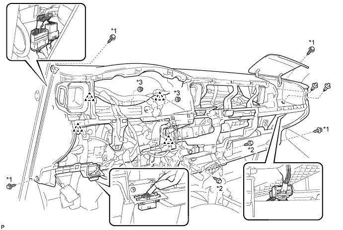
Text in Illustration *1 Bolt A *2 Screw B *1 Nut D - -
-
-
INSTALL FRONT PILLAR GARNISH RH
-
INSTALL FRONT PILLAR GARNISH LH
-
INSTALL ASSIST GRIP ASSEMBLY
-
INSTALL FRONT ASSIST GRIP PLUG NO. 1
-
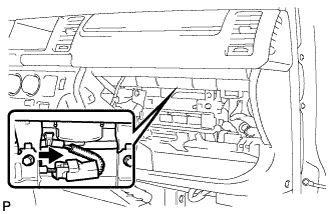
INSTALL HAZARD WARNING SIGNAL SWITCH ASSEMBLY
-
Connect the connector.
-
Attach the 2 claws to install the hazard warning signal switch.
-
-
INSTALL FRONT PASSENGER AIRBAG ASSEMBLY (w/ Front Passenger Airbag)
-
Engage the clamps and claws, and install the front passenger airbag assembly.
-

Install the instrument panel passenger airbag with the 2 bolts.
- Torque:
- 18 N*m { 184 kgf*cm, 13 ft.*lbf }
-
Connect the airbag connector.
-
Install the airbag connector to the reinforcement.
-
-
INSTALL GLOVE COMPARTMENT DOOR ASSEMBLY
-
Attach the 2 hinges to install the glove compartment door assembly.
-
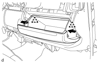
Push the positions indicated by the arrows in the illustration inward to attach the 2 stoppers.
-
-
INSTALL INSTRUMENT CLUSTER FINISH PANEL SUB-ASSEMBLY LOWER CENTER
-
w/ No. 3 Heater Control Knob
Attach the 2 claws to connect the air mix damper control cable sub-assembly to the No. 3 heater control knob.
-
Attach the 2 claws to connect the heater control cable sub-assembly to the heater control knob.
-
Attach the 2 claws to connect the air inlet damper control cable sub-assembly to the No. 2 heater control knob.
-
Connect the cable to the clamp.
-
Connect the connector.
-
Attach the 8 claws to install the instrument cluster finish panel sub-assembly lower center (air conditioning control assembly).
-
-
INSTALL SHIFT LOCK CONTROL UNIT ASSEMBLY (for Automatic Transmission)
For 1KD-FTV, 2KD-FTV Click here
For 1TR-FE Click here
For 2TR-FE Click here
-
INSTALL FLOOR SHIFT SHIFT LEVER ASSEMBLY (for Manual Transmission)
For 5L-E Click here
For 1KD-FTV, 2KD-FTV, 2TR-FE Click here
-
INSTALL INSTRUMENT PANEL FINISH PANEL LOWER CENTER
-
Attach the 8 claws to install the instrument panel finish panel lower center.
-
-
INSTALL SHIFTING HOLE COVER ASSEMBLY
-
for Manual Transmission:
Attach the 6 claws to install the shifting hole cover assembly.
-
for Automatic Transmission:
Attach the 8 claws to install the shifting hole cover assembly.
-
-
INSTALL SHIFT LEVER KNOB
-
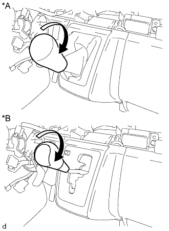
Text in Illustration *A for Manual Transmission *B for Automatic Transmission Turn the shift lever knob in the direction indicated by the arrow and install it.
-
-
INSTALL PARKING BRAKE HOLE COVER
-
Attach the 6 claws to install the parking brake hole cover.
-
-
INSTALL INSTRUMENT PANEL UNDER COVER SUB-ASSEMBLY NO. 1
-
Attach the 3 claws to instrument panel under cover sub-assembly No. 1.
-
Install the the 2 clips.
-
-
INSTALL INSTRUMENT PANEL FINISH PANEL LOWER
-
Connect the fuel lid lock control cable and bonnet (hood) control cable assembly to the instrument panel finish lower.
-
Attach the 4 clips to install the instrument panel finish panel lower.
-
Install the 2 clips.
-
-
INSTALL RADIO RECEIVER ASSEMBLY WITH BRACKET (w/ Radio Receiver)
-
INSTALL STEREO OPENING COVER WITH BRACKET (w/o Radio Receiver)
-
Install the stereo tuner opening cover with bracket with the 4 screws <C>.
-
-
INSTALL INSTRUMENT PANEL CUP HOLDER ASSEMBLY
-
Install the instrument panel cup holder assembly with the 3 screws <C>.
-
-
INSTALL COMBINATION METER ASSEMBLY
-
Attach the wire harness clamp and connect the 2 connectors.
-
Attach the 2 claws to install the combination meter assembly.
-
Install the 2 screws.
-
-
INSTALL INSTRUMENT CLUSTER FINISH PANEL SUB-ASSEMBLY
-
Attach the 6 claws and a hooks to install the instrument cluster finish panel sub-assembly.
-
-
INSTALL INSTRUMENT CLUSTER FINISH PANEL ASSEMBLY
-
Attach the 4 claws to install the instrument cluster finish panel assembly.
-
-
INSTALL INSTRUMENT CLUSTER FINISH PANEL GARNISH NO. 1
-
Attach the 3 claws to install the instrument cluster finish panel garnish No. 1.
-
-
INSTALL INSTRUMENT CLUSTER FINISH PANEL SUB-ASSEMBLY CENTER
-
for Standard Body:
Attach the 14 claws to install the instrument cluster finish panel sub-assembly center.
-
for Wide Body:
Attach the 16 claws to install the instrument cluster finish panel sub-assembly center.
-
-
INSTALL INSTRUMENT CLUSTER FINISH PANEL GARNISH NO. 2
-
Attach the 3 claws to install the instrument cluster finish panel garnish No. 2.
-
-
INSTALL TURN SIGNAL SWITCH WITH SPIRAL CABLE (w/ Airbag System)
-
Set the turn signal switch with spiral cable to the steering column.
-
While loosening the band clamp, attach the claw to install the turn signal switch with spiral cable.
-
Connect each connector.
-
-
INSTALL TURN SIGNAL SWITCH WITH WIPER SWITCH (w/o Airbag System)
-
Set the turn signal switch with wiper switch to the steering column.
-
While loosening the band clamp, attach the claw to install the turn signal switch with wiper switch.
-
Connect each connector.
-
-
INSTALL KEY CYLINDER LIGHT ASSEMBLY (w/ Key Cylinder Light)
-
Attach the claw to install the key cylinder light assembly.
-
-
INSTALL STEERING COLUMN COVER UPPER
-
Install the steering column cover upper.
-
-
INSTALL STEERING COLUMN COVER LOWER
-
Engage the 4 claws to install the steering column lower cover to the steering column upper cover.
-
Using a "TORX" socket wrench (T25), tighten the 2 screws.
-
-
INSTALL STEERING COLUMN COVER LOWER NO. 2 (w/ Smart Entry and Start System)
-
Install the 4 guide pins install the No. 2 steering column lower cover.
-
-
ADJUST SPIRAL CABLE SUB-ASSEMBLY (w/ Airbag System)
-
Check that the ignition switch is off.
-
Check that the cable is disconnected from the negative (-) battery terminal.
CAUTION:
Wait at least 90 seconds after disconnecting the cable from the negative (-) battery terminal to disable the SRS system.
-
Check that the spiral cable sub-assembly is center position.
OK The connector is at the top. The colored roller or the top of the flat cable U-turn can be checked from the check window. 
Text in Illustration *A Colored Roller (Visible Type), w/ Steering Pad Switch *B Flat Cable (Visible Type) *C Colored Roller (Visible Type), w/o Steering Pad Switch - - *a Check Window *b Colored Roller *c Top of Flat Cable U-turn - - -
If the spiral cable sub-assembly is not centered, center it.
Note
Failure to observe the following precautions may result in damage to the spiral cable sub-assembly.
-
When rotating the spiral cable sub-assembly, make sure to push on the interlock to release the interlock.
-
Do not turn the spiral cable sub-assembly using the airbag wire harness.
-
Do not forcibly rotate the part.
-

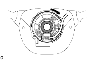
While pushing on the interlock indicated in the illustration. Make sure to rotate the spiral cable sub-assembly counterclockwise slowly by hand until it stops.
Note
Make sure to rotate the spiral cable sub-assembly counterclockwise. If rotated clockwise, it may be damaged or centering may no longer be possible.
Tech Tips
The interlock operates at the top and bottom of the connector.
Text in Illustration 
Interlock 
Counterclockwise -

If the spiral cable sub-assembly stops rotating and the connector has moved past the bottom, return the connector to the bottom as shown in the illustration.
-
While pushing on the interlock, rotate the spiral cable sub-assembly clockwise approximately 2.5 times to move the connector from the bottom to the top.
Note
If the connector is rotated clockwise from the bottom 5 times or more, the spiral cable sub-assembly may be damaged.
Tech Tips
The interlock operates at the top and bottom of the connector.
Text in Illustration Interlock Counterclockwise -
Check that the spiral cable sub-assembly is center position.
OK The connector is at the top. The colored roller or the top of the flat cable U-turn can be checked from the check window.
Text in Illustration *A Colored Roller (Visible Type), w/ Steering Pad Switch *B Flat Cable (Visible Type) *C Colored Roller (Visible Type), w/o Steering Pad Switch - - *a Check Window *b Colored Roller *c Top of Flat Cable U-turn - - Note
If the spiral cable sub-assembly cannot be centered, it is possible that the spiral cable sub-assembly is broken. Replace the spiral cable sub-assembly with a new one.
-
-
-
INSTALL STEERING WHEEL ASSEMBLY
-
Align the matchmarks on the steering wheel assembly and the steering column assembly.
-
Install the steering wheel set nut.
- Torque:
- 50 N*m { 510 kgf*cm, 37 ft.*lbf }
-
Connect the connectors.
-
-
INSTALL STEERING PAD (w/o Airbag System)
-
Connect the horn connector.
-
Using a "TORX" socket wrench (T30), tighten the 2 screws.
- Torque:
- 1.5 N*m { 15 kgf*cm, 13 in.*lbf }
-
-
INSTALL STEERING PAD (w/ Airbag System)
-
Check that the ignition switch is off.
-
Check that the cable is disconnected from the negative (-) battery terminal.
CAUTION:
Wait at least 90 seconds after disconnecting the cable from the negative (-) battery terminal to disable the SRS system.
-
Support the steering pad with one hand.
-
Connect the airbag connector to the steering pad.
Note
When connecting any airbag connector, take care not to damage the airbag wire harness.
-
Push in the airbag connector lock to connect the airbag connector.
-
Connect the horn connector to the steering pad.
-
Install the steering pad.
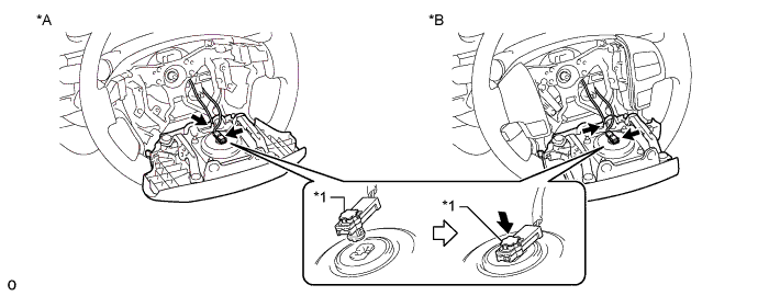
Text in Illustration *A w/o Steering Pad Switch *B w/ Steering Pad Switch *1 Connector Lock - - -
Using a T30 "TORX" socket wrench, tighten the 2 "TORX" screws.
- Torque:
- 8.8 N*m { 90 kgf*cm, 78 in.*lbf }
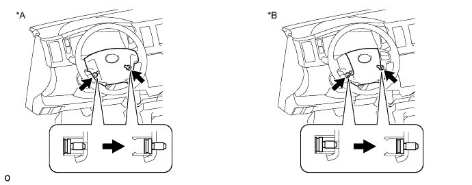
Text in Illustration *A w/o Steering Pad Switch *B w/ Steering Pad Switch
-
-
INSTALL STEERING WHEEL COVER LOWER NO. 3
-
INSTALL STEERING WHEEL COVER LOWER NO. 2
-
CONNECT CABLE TO NEGATIVE BATTERY TERMINAL
Note
When disconnecting the cable, some systems need to be initialized after the cable is reconnected Click here.
-
INSPECT STEERING PAD (w/ Airbag System)
-
With the steering pad installed on the vehicle, perform a visual check. If there are any defects as mentioned below, replace the steering pad with a new one:
Cuts, small cracks or marked discoloration on the steering pad top surface or in the grooved portion.
-
Make sure that the horn sounds.
Tech Tips
If the horn does not sound, inspect the horn system Click here.
-
-
INSPECT SRS WARNING LIGHT (w/ Airbag System)