SFI SYSTEM, Diagnostic DTC:P0461,P0462 and P0463
| DTC Code | DTC Name |
|---|---|
| P0461 | Fuel Level Sensor "A" Circuit Range / Performance |
| P0462 | Fuel Level Sensor "A" Circuit Low |
| P0463 | Fuel Level Sensor "A" Circuit High |
DESCRIPTION
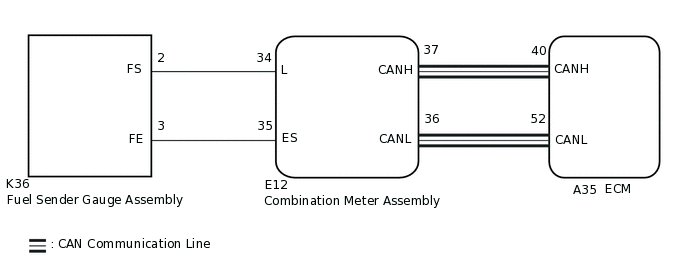
The fuel sender gauge assembly signal is sent from the combination meter to the ECM via CAN communication.
DTC No. |
Detection Item |
DTC Detection Condition |
Trouble Area |
MIL |
Memory |
|---|---|---|---|---|---|
P0461 |
Fuel Level Sensor "A" Circuit Range / Performance |
Fuel sender gauge assembly signal failure (ECM receives malfunction signal via CAN communication). |
|
Does not come on |
DTC stored |
P0462 |
Fuel Level Sensor "A" Circuit Low |
Short to ground in fuel sender gauge assembly circuit. |
|
Does not come on |
DTC stored |
P0463 |
Fuel Level Sensor "A" Circuit High |
Open or short in fuel sender gauge assembly circuit. |
|
Does not come on |
DTC stored |
MONITOR DESCRIPTION
These DTCs are stored when a malfunction is detected in the fuel sender gauge assembly circuit. If there is an open or short in the fuel sender gauge assembly circuit, or the fuel sender gauge signal is abnormal, the ECM will store a DTC.
WIRING DIAGRAM
CAUTION / NOTICE / HINT
Inspection the fuses for circuits related to this system before performing the following procedure.
PROCEDURE
CHECK ANY OTHER DTCS OUTPUT (IN ADDITION TO DTC P0461, P0462 AND/OR P0463)
Connect the GTS to the DLC3.
Turn the ignition switch to ON.
Turn the GTS on.
Enter the following menus: System Select / Health Check.
Check for DTCs.
Result
Result
Proceed to
DTC P0461, P0462 and/or P0463 is output
A
DTC P0461, P0462 and/or P0463 and other DTCs are output
B
Tip:If any DTCs other than P0461, P0462 and/or P0463 are output, troubleshoot those DTCs first.
B GO TO DTC CHART
INSPECT FUEL SENDER GAUGE ASSEMBLY
Inspect the fuel sender gauge assembly.
Result
Proceed to
OK
NG
CHECK HARNESS AND CONNECTOR (FUEL SENDER GAUGE ASSEMBLY - COMBINATION METER ASSEMBLY)
Disconnect the fuel sender gauge assembly connector.
Disconnect the combination meter assembly connector.
Measure the resistance according to the value(s) in the table below.
Standard Resistance
Tester Connection
Condition
Specified Condition
K36-2 (FS) - E12-34 (L)
Always
Below 1 Ω
K36-3 (FE) - E12-35 (ES)
Always
Below 1 Ω
K36-2 (FS) or E12-34 (L) - Body ground and other terminals
Always
10 kΩ or higher
K36-3 (FE) or E12-35 (ES) - Body ground and other terminals
Always
10 kΩ or higher
Result
Proceed to
OK
NG
NG REPAIR OR REPLACE HARNESS OR CONNECTOR