AUDIO AND VISUAL SYSTEM(w/o Multi-display) AVC-LAN Circuit
| DTC Code | DTC Name |
|---|---|
| AVC-LAN Circuit |
DESCRIPTION
Each unit of the audio system connected to the AVC-LAN (communication bus) transfers the signal of each switch by communication.
When a short to +B or short to ground occurs in this AVC-LAN, the audio system will not function normally as the communication is discontinued.
WIRING DIAGRAM
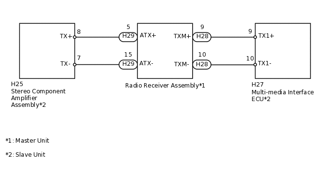
PROCEDURE
INSPECT RADIO RECEIVER ASSEMBLY
-
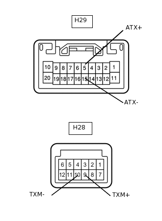
Disconnect the H29 and H28 radio receiver assembly connectors.
Measure the resistance according to the value(s) in the table below.
Standard Resistance
Tester Connection
Condition
Specified Condition
H29-5 (ATX+) - H29-15 (ATX-)
Always
60 to 80 Ω
H28-9 (TXM+) - H28-10 (TXM-)
Always
60 to 80 Ω
Result
Result
OK
NG
-
CHECK HARNESS AND CONNECTOR (RADIO RECEIVER - COMPONENT WHICH HAS STORED THIS CODE)
Referring to the wiring diagram, check the AVC-LAN circuit between the radio receiver assembly and the component which has stored this code.
Disconnect all connectors between the radio receiver assembly and the component which has stored this code.
Check for an open or short in the AVC-LAN circuit between the radio receiver assembly and the component which has stored this code.
OK
There is no open or short circuit.
Result
Result
OK
NG
NG REPAIR OR REPLACE HARNESS OR CONNECTOR