COMBUSTION TYPE POWER HEATER SYSTEM Power Heater Switch Circuit
| DTC Code | DTC Name |
|---|---|
| Power Heater Switch Circuit |
DESCRIPTION
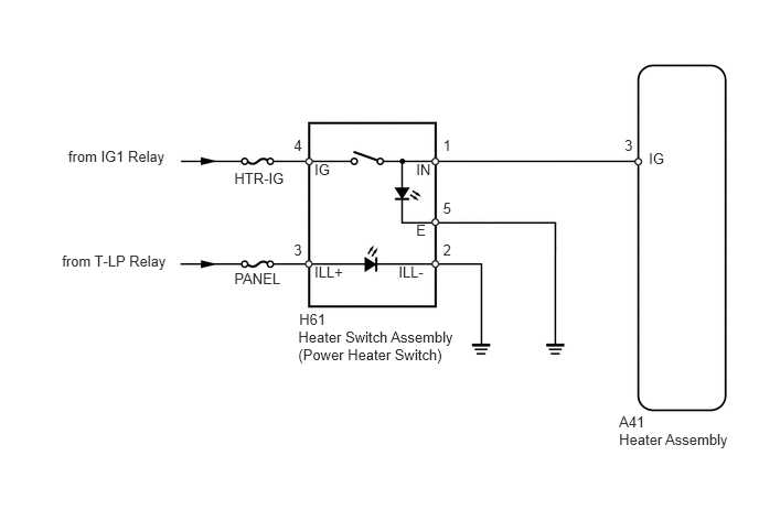
When the power heater switch is turned on, the heater assembly (ECU) sends a drive signal to the heater pump assembly. The heater assembly then receives the fuel necessary for combustion and starts operating.
WIRING DIAGRAM
CAUTION / NOTICE / HINT
Inspect the fuses for circuits related to this system before performing the following inspection procedure.
Before performing the following procedures, check the battery and generator assembly and confirm that they are operating normally.
PROCEDURE
INSPECT HEATER SWITCH ASSEMBLY (POWER HEATER SWITCH)
-
Remove the power heater switch (Click here).
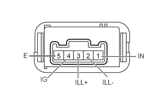
Measure the resistance according to the value(s) in the table below.
Standard Resistance
Tester Connection
Switch Condition
Specified Condition
4 (IG) - 1 (IN)
Power heater switch on
Below 1 Ω
4 (IG) - 1 (IN)
Power heater switch off
10 kΩ or higher
Apply battery voltage to the power heater switch and check that the operation indicator comes on.
OK
Measurement Condition
Specified Condition
Battery positive (+) → Terminal 1 (IN)
Battery negative (-) → Terminal 5 (E)
Indicator comes on
Apply battery voltage to the power heater switch and check that the illumination comes on.
OK
Measurement Condition
Specified Condition
Battery positive (+) → Terminal 3 (ILL+)
Battery negative (-) → Terminal 2 (ILL-)
Illumination comes on
-
CHECK HARNESS AND CONNECTOR (HEATER SWITCH - BODY GROUND)
-
Disconnect the H61 switch connector.
Measure the resistance according to the value(s) in the table below.
Standard Resistance
Tester Connection
Condition
Specified Condition
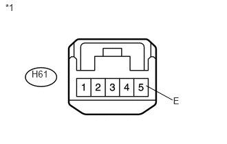
H61-5 (E) - Body ground
Always
Below 1 Ω
Table 1. Text in Illustration *1
Front view of wire harness connector
(Heater Switch Assembly [Power Heater Switch])
REPAIR OR REPLACE HARNESS OR CONNECTOR
-
CHECK HARNESS AND CONNECTOR (HEATER ASSEMBLY - BATTERY)
-
Disconnect the A41 heater connector.
Measure the voltage according to the value(s) in the table below.
Standard Voltage
Tester Connection
Switch Condition
Specified Condition
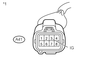
A41-3 (IG) - Body ground
Ignition switch ON
Power heater switch on
11 to 14 V
A41-3 (IG) - Body ground
Ignition switch ON
Power heater switch off
Below 1 V
Table 2. Text in Illustration *1
Front view of wire harness connector
(to Heater Assembly)
REPAIR OR REPLACE HARNESS OR CONNECTOR
-