METER / GAUGE SYSTEM, Diagnostic DTC:B1507 and B1508
| DTC Code | DTC Name |
|---|---|
| B1507 | Open in Turn Signal Circuit |
| B1508 | Short in Turn Signal / Hazard Flasher Circuit |
DESCRIPTION
These DTCs are stored when the combination meter assembly detects an open in a turn signal light circuit, a short in a turn signal light circuit, or a short in the hazard warning light circuit.
DTC No. |
Detection Item |
DTC Detection Condition |
Trouble Area |
Memory |
Note |
|---|---|---|---|---|---|
B1507 |
Open in Turn Signal Circuit |
When IG voltage is 9.5 V or more and the following condition is detected:
|
|
DTC stored |
- |
B1508 |
Short in Turn Signal / Hazard Flasher Circuit |
When IG voltage is 9.5 V or more and the following condition is detected:
|
|
DTC stored |
- |
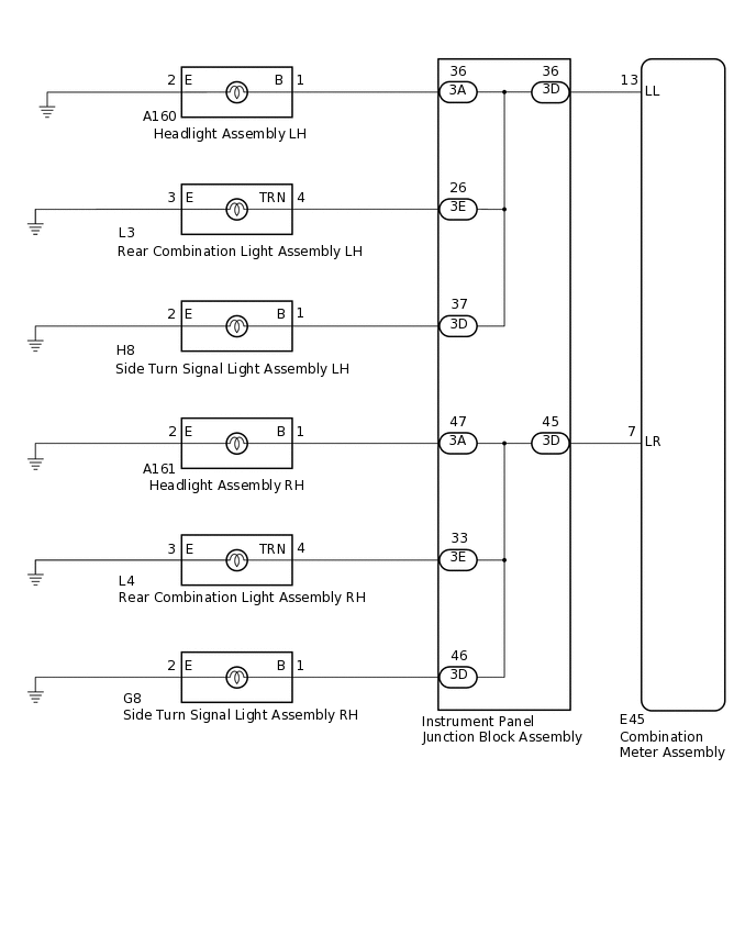
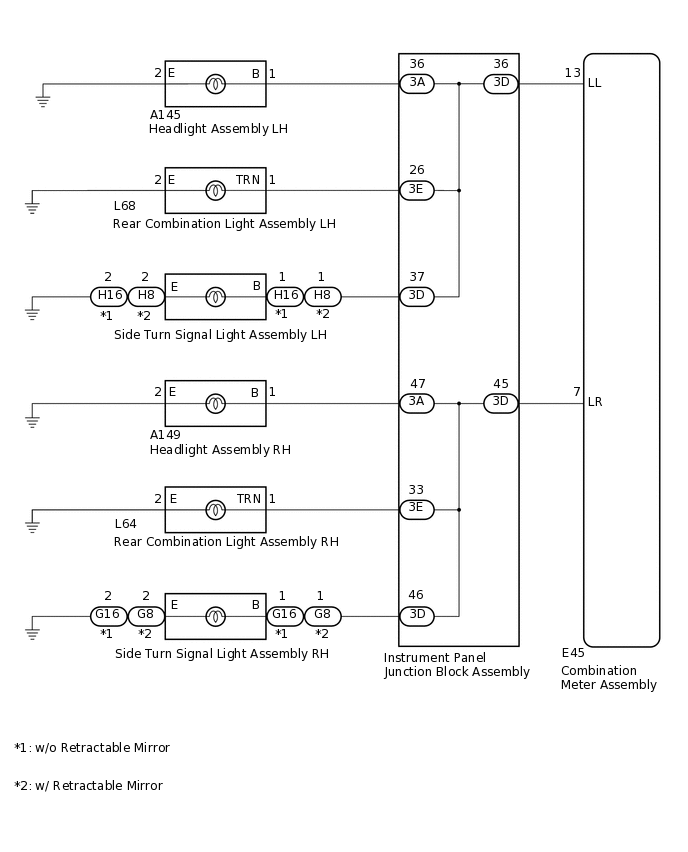
WIRING DIAGRAM
for Hatchback
for Sedan
CAUTION / NOTICE / HINT
Inspect the bulbs for this system before performing the following procedure.
Rear combination light assembly (for Sedan):Click hereClick here
Rear combination light assembly (for Hatchback):Click here
PROCEDURE
CONFIRM VEHICLE TYPE
Choose the model to be inspected.
Result
Result
Proceed to
for Hatchback
A
for Sedan
B
B INSPECT LIGHTSClick here
INSPECT LIGHTS
Inspect the illumination of each turn signal light.
Result
Result
Proceed to
Turn signal lights for one side do not illuminate.
A
Front turn signal light does not illuminate.
B
Rear turn signal light does not illuminate.
C
Side turn signal light does not illuminate.
D
B CHECK HARNESS AND CONNECTOR (HEADLIGHT ASSEMBLY - INSTRUMENT PANEL JUNCTION BLOCK ASSEMBLY)Click here
C CHECK HARNESS AND CONNECTOR (REAR COMBINATION LIGHT ASSEMBLY - INSTRUMENT PANEL JUNCTION BLOCK ASSEMBLY)Click here
D CHECK HARNESS AND CONNECTOR (SIDE TURN SIGNAL LIGHT ASSEMBLY - INSTRUMENT PANEL JUNCTION BLOCK ASSEMBLY)Click here
CHECK HARNESS AND CONNECTOR (COMBINATION METER ASSEMBLY - INSTRUMENT PANEL JUNCTION BLOCK ASSEMBLY)
Disconnect the E45 combination meter assembly connector.
Disconnect the 3D instrument panel junction block assembly connector.
Measure the resistance according to the value(s) in the table below.
Standard Resistance (Check for Open)
Table 1. for LH Tester Connection
Condition
Specified Condition
E45-13 (LL) - 3D-36
Always
Below 1 Ω
Table 2. for RH Tester Connection
Condition
Specified Condition
E45-7 (LR) - 3D-45
Always
Below 1 Ω
Standard Resistance (Check for Short)
Table 3. for LH Tester Connection
Condition
Specified Condition
E45-13 (LL) - Body ground
Always
10 kΩ or higher
Table 4. for RH Tester Connection
Condition
Specified Condition
E45-7 (LR) - Body ground
Always
10 kΩ or higher
Result
Proceed to
OK
NG
OK INSPECT INSTRUMENT PANEL JUNCTION BLOCK ASSEMBLYClick here
NG REPAIR OR REPLACE HARNESS OR CONNECTOR
CHECK HARNESS AND CONNECTOR (HEADLIGHT ASSEMBLY - INSTRUMENT PANEL JUNCTION BLOCK ASSEMBLY)
Disconnect the A160*1 or A161*2 headlight assembly connector.
*1: for LH
*2: for RH
Disconnect the 3A instrument panel junction block assembly connector.
Measure the resistance according to the value(s) in the table below.
Standard Resistance (Check for Open)
Table 5. for LH Tester Connection
Condition
Specified Condition
A160-1 (B) - 3A-36
Always
Below 1 Ω
A160-2 (E) - Body ground
Always
Below 1 Ω
Table 6. for RH Tester Connection
Condition
Specified Condition
A161-1 (B) - 3A-47
Always
Below 1 Ω
A161-2 (E) - Body ground
Always
Below 1 Ω
Standard Resistance (Check for Short)
Table 7. for LH Tester Connection
Condition
Specified Condition
A160-1 (B) - Body ground
Always
10 kΩ or higher
Table 8. for RH Tester Connection
Condition
Specified Condition
A161-1 (B) - Body ground
Always
10 kΩ or higher
Result
Proceed to
OK
NG
OK INSPECT INSTRUMENT PANEL JUNCTION BLOCK ASSEMBLYClick here
NG REPAIR OR REPLACE HARNESS OR CONNECTOR
CHECK HARNESS AND CONNECTOR (REAR COMBINATION LIGHT ASSEMBLY - INSTRUMENT PANEL JUNCTION BLOCK ASSEMBLY)
Disconnect the L3*1 or L4*2 rear combination light assembly connector.
*1: for LH
*2: for RH
Disconnect the 3E instrument panel junction block assembly connector.
Measure the resistance according to the value(s) in the table below.
Standard Resistance (Check for Open)
Table 9. for LH Tester Connection
Condition
Specified Condition
L3-4 (TRN) - 3E-26
Always
Below 1 Ω
L3-3 (E) - Body ground
Always
Below 1 Ω
Table 10. for RH Tester Connection
Condition
Specified Condition
L4-4 (TRN) - 3E-33
Always
Below 1 Ω
L4-3 (E) - Body ground
Always
Below 1 Ω
Standard Resistance (Check for Short)
Table 11. for LH Tester Connection
Condition
Specified Condition
L3-4 (TRN) - Body ground
Always
10 kΩ or higher
Table 12. for RH Tester Connection
Condition
Specified Condition
L4-4 (TRN) - Body ground
Always
10 kΩ or higher
Result
Proceed to
OK
NG
OK INSPECT INSTRUMENT PANEL JUNCTION BLOCK ASSEMBLYClick here
NG REPAIR OR REPLACE HARNESS OR CONNECTOR
CHECK HARNESS AND CONNECTOR (SIDE TURN SIGNAL LIGHT ASSEMBLY - INSTRUMENT PANEL JUNCTION BLOCK ASSEMBLY)
Disconnect the H8*1 or G8*2 side turn signal light assembly connector.
*1: for LH
*2: for RH
Disconnect the 3D instrument panel junction block assembly connector.
Measure the resistance according to the value(s) in the table below.
Standard Resistance (Check for Open)
Table 13. for LH Tester Connection
Condition
Specified Condition
H8-1 (B) - 3D-37
Always
Below 1 Ω
H8-2 (E) - Body ground
Always
Below 1 Ω
Table 14. for RH Tester Connection
Condition
Specified Condition
G8-1 (B) - 3D-46
Always
Below 1 Ω
G8-2 (E) - Body ground
Always
Below 1 Ω
Standard Resistance (Check for Short)
Table 15. for LH Tester Connection
Condition
Specified Condition
H8-1 (B) - Body ground
Always
10 kΩ or higher
Table 16. for RH Tester Connection
Condition
Specified Condition
G8-1 (B) - Body ground
Always
10 kΩ or higher
Result
Proceed to
OK
NG
NG REPAIR OR REPLACE HARNESS OR CONNECTOR
INSPECT INSTRUMENT PANEL JUNCTION BLOCK ASSEMBLY
Remove the main body ECU (multiplex network body ECU) from the instrument panel junction block assembly.
for LHD:Click here
for RHD:Click here
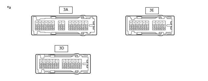
*a
Component without harness connected
(Instrument Panel Junction Block Assembly)
-
-
Front turn signal light
Measure the resistance according to the value(s) in the table below.
Standard Resistance
Table 17. for LH Tester Connection
Condition
Specified Condition
3D-36 - 3A-36
Always
Below 1 Ω
Table 18. for RH Tester Connection
Condition
Specified Condition
3D-45 - 3A-47
Always
Below 1 Ω
Rear turn signal light
Measure the resistance according to the value(s) in the table below.
Standard Resistance
Table 19. for LH Tester Connection
Condition
Specified Condition
3D-36 - 3E-26
Always
Below 1 Ω
Table 20. for RH Tester Connection
Condition
Specified Condition
3D-45 - 3E-33
Always
Below 1 Ω
Side turn signal light
Measure the resistance according to the value(s) in the table below.
Standard Resistance
Table 21. for LH Tester Connection
Condition
Specified Condition
3D-36 - 3D-37
Always
Below 1 Ω
Table 22. for RH Tester Connection
Condition
Specified Condition
3D-45 - 3D-46
Always
Below 1 Ω
Result
Proceed to
OK
NG
OK REPLACE COMBINATION METER ASSEMBLY
for Hatchback, Wagon:Click here
for Sedan:Click hereClick here
INSPECT LIGHTS
Inspect the illumination of each turn signal light.
Result
Result
Proceed to
Turn signal lights for one side do not illuminate.
A
Front turn signal light does not illuminate.
B
Rear turn signal light does not illuminate.
C
Side turn signal light does not illuminate.
D
B CHECK HARNESS AND CONNECTOR (HEADLIGHT ASSEMBLY - INSTRUMENT PANEL JUNCTION BLOCK ASSEMBLY)Click here
C CHECK HARNESS AND CONNECTOR (REAR COMBINATION LIGHT ASSEMBLY - INSTRUMENT PANEL JUNCTION BLOCK ASSEMBLY)Click here
D CHECK HARNESS AND CONNECTOR (SIDE TURN SIGNAL LIGHT ASSEMBLY - INSTRUMENT PANEL JUNCTION BLOCK ASSEMBLY)Click here
CHECK HARNESS AND CONNECTOR (COMBINATION METER ASSEMBLY - INSTRUMENT PANEL JUNCTION BLOCK ASSEMBLY)
Disconnect the E45 combination meter assembly connector.
Disconnect the 3D instrument panel junction block assembly connector.
Measure the resistance according to the value(s) in the table below.
Standard Resistance (Check for Open)
Table 23. for LH Tester Connection
Condition
Specified Condition
E45-13 (LL) - 3D-36
Always
Below 1 Ω
Table 24. for RH Tester Connection
Condition
Specified Condition
E45-7 (LR) - 3D-45
Always
Below 1 Ω
Standard Resistance (Check for Short)
Table 25. for LH Tester Connection
Condition
Specified Condition
E45-13 (LL) - Body ground
Always
10 kΩ or higher
Table 26. for RH Tester Connection
Condition
Specified Condition
E45-7 (LR) - Body ground
Always
10 kΩ or higher
Result
Proceed to
OK
NG
OK INSPECT INSTRUMENT PANEL JUNCTION BLOCK ASSEMBLYClick here
NG REPAIR OR REPLACE HARNESS OR CONNECTOR
CHECK HARNESS AND CONNECTOR (HEADLIGHT ASSEMBLY - INSTRUMENT PANEL JUNCTION BLOCK ASSEMBLY)
Disconnect the A145*1 or A149*2 headlight assembly connector.
*1: for LH
*2: for RH
Disconnect the 3A instrument panel junction block assembly connector.
Measure the resistance according to the value(s) in the table below.
Standard Resistance (Check for Open)
Table 27. for LH Tester Connection
Condition
Specified Condition
A145-1 (B) - 3A-36
Always
Below 1 Ω
A145-2 (E) - Body ground
Always
Below 1 Ω
Table 28. for RH Tester Connection
Condition
Specified Condition
A149-1 (B) - 3A-47
Always
Below 1 Ω
A149-2 (E) - Body ground
Always
Below 1 Ω
Standard Resistance (Check for Short)
Table 29. for LH Tester Connection
Condition
Specified Condition
A145-1 (B) - Body ground
Always
10 kΩ or higher
Table 30. for RH Tester Connection
Condition
Specified Condition
A149-1 (B) - Body ground
Always
10 kΩ or higher
Result
Proceed to
OK
NG
OK INSPECT INSTRUMENT PANEL JUNCTION BLOCK ASSEMBLYClick here
NG REPAIR OR REPLACE HARNESS OR CONNECTOR
CHECK HARNESS AND CONNECTOR (REAR COMBINATION LIGHT ASSEMBLY - INSTRUMENT PANEL JUNCTION BLOCK ASSEMBLY)
Disconnect the L68*1 or L64*2 rear combination light assembly connector.
*1: for LH
*2: for RH
Disconnect the 3E instrument panel junction block assembly connector.
Measure the resistance according to the value(s) in the table below.
Standard Resistance (Check for Open)
Table 31. for LH Tester Connection
Condition
Specified Condition
L68-1 (TRN) - 3E-26
Always
Below 1 Ω
L68-2 (E) - Body ground
Always
Below 1 Ω
Table 32. for RH Tester Connection
Condition
Specified Condition
L64-1 (TRN) - 3E-33
Always
Below 1 Ω
L64-2 (E) - Body ground
Always
Below 1 Ω
Standard Resistance (Check for Short)
Table 33. for LH Tester Connection
Condition
Specified Condition
L68-1 (TRN) - Body ground
Always
10 kΩ or higher
Table 34. for RH Tester Connection
Condition
Specified Condition
L64-1 (TRN) - Body ground
Always
10 kΩ or higher
Result
Proceed to
OK
NG
OK INSPECT INSTRUMENT PANEL JUNCTION BLOCK ASSEMBLYClick here
NG REPAIR OR REPLACE HARNESS OR CONNECTOR
CHECK HARNESS AND CONNECTOR (SIDE TURN SIGNAL LIGHT ASSEMBLY - INSTRUMENT PANEL JUNCTION BLOCK ASSEMBLY)
w/o Retractable Mirror
Disconnect the H16*1 or G16*2 side turn signal light assembly connector.
*1: for LH
*2: for RH
Disconnect the 3D instrument panel junction block assembly connector.
Measure the resistance according to the value(s) in the table below.
Standard Resistance (Check for Open)
Table 35. for LH Tester Connection
Condition
Specified Condition
H16-1 (B) - 3D-37
Always
Below 1 Ω
H16-2 (E) - Body ground
Always
Below 1 Ω
Table 36. for RH Tester Connection
Condition
Specified Condition
G16-1 (B) - 3D-46
Always
Below 1 Ω
G16-2 (E) - Body ground
Always
Below 1 Ω
Standard Resistance (Check for Short)
Table 37. for LH Tester Connection
Condition
Specified Condition
H16-1 (B) - Body ground
Always
10 kΩ or higher
Table 38. for RH Tester Connection
Condition
Specified Condition
G16-1 (B) - Body ground
Always
10 kΩ or higher
w/ Retractable Mirror
Disconnect the H8*1 or G8*2 side turn signal light assembly connector.
*1: for LH
*2: for RH
Disconnect the 3D instrument panel junction block assembly connector.
Measure the resistance according to the value(s) in the table below.
Standard Resistance (Check for Open)
Table 39. for LH Tester Connection
Condition
Specified Condition
H8-1 (B) - 3D-37
Always
Below 1 Ω
H8-2 (E) - Body ground
Always
Below 1 Ω
Table 40. for RH Tester Connection
Condition
Specified Condition
G8-1 (B) - 3D-46
Always
Below 1 Ω
G8-2 (E) - Body ground
Always
Below 1 Ω
Standard Resistance (Check for Short)
Table 41. for LH Tester Connection
Condition
Specified Condition
H8-1 (B) - Body ground
Always
10 kΩ or higher
Table 42. for RH Tester Connection
Condition
Specified Condition
G8-1 (B) - Body ground
Always
10 kΩ or higher
Result
Proceed to
OK
NG
NG REPAIR OR REPLACE HARNESS OR CONNECTOR
INSPECT INSTRUMENT PANEL JUNCTION BLOCK ASSEMBLY
Remove the main body ECU (multiplex network body ECU) from the instrument panel junction block assembly.
for LHD:Click here
for RHD:Click here
*a
Component without harness connected
(Instrument Panel Junction Block Assembly)
-
-
Front turn signal light
Measure the resistance according to the value(s) in the table below.
Standard Resistance
Table 43. for LH Tester Connection
Condition
Specified Condition
3D-36 - 3A-36
Always
Below 1 Ω
Table 44. for RH Tester Connection
Condition
Specified Condition
3D-45 - 3A-47
Always
Below 1 Ω
Rear turn signal light
Measure the resistance according to the value(s) in the table below.
Standard Resistance
Table 45. for LH Tester Connection
Condition
Specified Condition
3D-36 - 3E-26
Always
Below 1 Ω
Table 46. for RH Tester Connection
Condition
Specified Condition
3D-45 - 3E-33
Always
Below 1 Ω
Side turn signal light
Measure the resistance according to the value(s) in the table below.
Standard Resistance
Table 47. for LH Tester Connection
Condition
Specified Condition
3D-36 - 3D-37
Always
Below 1 Ω
Table 48. for RH Tester Connection
Condition
Specified Condition
3D-45 - 3D-46
Always
Below 1 Ω
Result
Proceed to
OK
NG
OK REPLACE COMBINATION METER ASSEMBLY
for Hatchback, Wagon:Click here
for Sedan:Click hereClick here