EXHAUST GAS TEMPERATURE SENSOR(w/ Glow Plug Controller) REMOVAL
PROCEDURE
PRECAUTION
Note:After turning the ignition switch off, waiting time may be required before disconnecting the cable from the negative (-) battery terminal. Therefore, make sure to read the disconnecting the cable from the negative (-) battery terminal notices before proceeding with work.
DISCONNECT CABLE FROM NEGATIVE BATTERY TERMINAL
Note:When disconnecting the cable, some systems need to be initialized after the cable is reconnected.
REMOVE NO. 1 ENGINE COVER (w/ No. 1 Engine Cover)
REMOVE WINDSHIELD WIPER MOTOR AND LINK ASSEMBLY
REMOVE WATER GUARD PLATE LH
for LHD:
for RHD:
REMOVE NO. 2 HEATER AIR DUCT SPLASH SHIELD SEAL
for LHD:
for RHD:
REMOVE OUTER COWL TOP PANEL
for LHD:
for RHD:
REMOVE NO. 1 WIRE HARNESS HEAT INSULATOR
REMOVE WIRE HARNESS CLAMP BRACKET
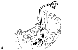
REMOVE EXHAUST GAS TEMPERATURE SENSOR
Note:If the exhaust gas temperature sensor is dropped, replace it with a new one.
-
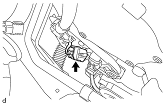
Disconnect the exhaust gas temperature sensor connector.
-
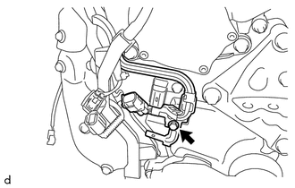
Remove the bolt and wire harness clamp bracket from the timing chain cover assembly.
-
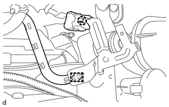
Disengage the claw to disconnect the exhaust gas temperature sensor connector from the wire harness clamp bracket.
Disengage the clamp to disconnect the wire harness from the wire harness clamp bracket.
-
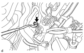
Using a 14 mm union nut wrench, remove the exhaust gas temperature sensor from the No. 2 exhaust manifold.
-
REMOVE DIFFERENTIAL PRESSURE SENSOR ASSEMBLY
REMOVE SENSOR BRACKET
REMOVE NO. 2 ENGINE COVER BRACKET
SEPARATE NO. 2 HOSE TO HOSE TUBE (for LHD)
SEPARATE NO. 2 HOSE TO HOSE TUBE (for RHD)
REMOVE BATTERY
REMOVE AIR CLEANER CAP SUB-ASSEMBLY
REMOVE AIR CLEANER CASE SUB-ASSEMBLY
REMOVE NO. 1 AIR TUBE
REMOVE NO. 1 TURBO INSULATOR
REMOVE FRONT DRIVE SHAFT ASSEMBLY RH
REMOVE FRONT CENTER FLOOR BRACE SUB-ASSEMBLY
REMOVE FRONT EXHAUST PIPE ASSEMBLY
REMOVE FRONT NO. 1 FLOOR HEAT INSULATOR
REMOVE NO. 5 MANIFOLD SUPPORT BRACKET
REMOVE FRONT SUSPENSION CROSSMEMBER SUB-ASSEMBLY
REMOVE NO. 4 MANIFOLD SUPPORT BRACKET
REMOVE DRIVE SHAFT HEAT INSULATOR SUB-ASSEMBLY
REMOVE NO. 2 EXHAUST MANIFOLD
REMOVE NO. 2 EXHAUST GAS TEMPERATURE SENSOR
Note:If the No. 2 exhaust gas temperature sensor is dropped, replace it with a new one.
-
Using a 14 mm union nut wrench, remove the No. 2 exhaust gas temperature sensor from the No. 2 exhaust manifold.
-