AUDIO AND VISUAL SYSTEM(for Radio and Display Type) Microphone Circuit between Microphone and Radio Receiver
| DTC Code | DTC Name |
|---|---|
| Microphone Circuit between Microphone and Radio Receiver |
DESCRIPTION
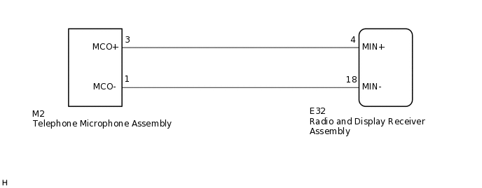
Using this circuit, the radio and display receiver assembly sends power to the telephone microphone assembly, and the telephone microphone assembly sends microphone signals to the radio and display receiver assembly.
WIRING DIAGRAM
PROCEDURE
CHECK MICROPHONE (OPERATION CHECK)
-
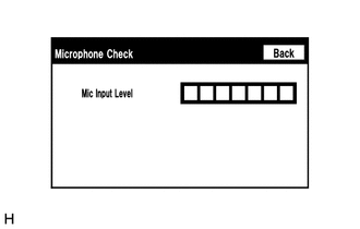
Enter the "Microphone Check" screen. Refer to Check Microphone in Operation Check.
When a voice is input into the microphone, check that the microphone input level meter changes according to the input voice.
OK
Check result is normal.
Result
Proceed to
OK
NG
-
CHECK HARNESS AND CONNECTOR (RADIO AND DISPLAY RECEIVER ASSEMBLY - TELEPHONE MICROPHONE ASSEMBLY)
Disconnect the E32 radio and display receiver assembly connector.
Disconnect the M2 telephone microphone assembly connector.
Measure the resistance according to the value(s) in the table below.
Standard Resistance
Tester Connection
Condition
Specified Condition
E32-4 (MIN+) - M2-3 (MCO+)
Always
Below 1 Ω
E32-18 (MIN-) - M2-1 (MCO-)
Always
Below 1 Ω
E32-4 (MIN+) - Body ground
Always
Below 20 kΩ
E32-18 (MIN-) - Body ground
Always
Below 1 Ω
Result
Proceed to
OK
NG
NG REPAIR OR REPLACE HARNESS OR CONNECTOR
INSPECT RADIO AND DISPLAY RECEIVER ASSEMBLY
Disconnect the E32 radio and display receiver assembly connector.
-
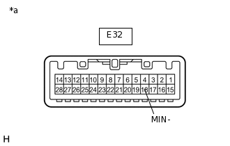
*a
Component without harness connected
(Radio and Display Receiver Assembly)
Measure the resistance according to the value(s) in the table below.
Standard Resistance
Tester Connection
Condition
Specified Condition
E32-18 (MIN-) - Body ground
Always
Below 1 Ω
Result
Proceed to
OK
NG
INSPECT TELEPHONE MICROPHONE ASSEMBLY
Turn the ignition switch to ACC.
-
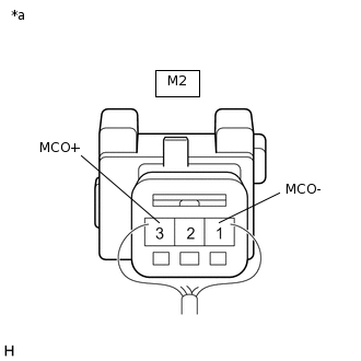
*a
Component with harness connected
(Telephone Microphone Assembly)
Connect an oscilloscope to terminals 3 (MCO+) and 1 (MCO-) of the M2 telephone microphone assembly connector.
Check the waveform of the telephone microphone assembly using the oscilloscope.
Result
Result
Proceed to
A waveform synchronized with the voice input to the telephone microphone assembly is output.
A
A waveform synchronized with the voice input to the telephone microphone assembly is not output.
B