БЛОК ДВИГАТЕЛЯ ПОВТОРНАЯ СБОРКА
Tech Tips
-
Thoroughly clean all parts to be assembled.
-
Before installing the parts, apply new engine oil to all sliding and rotating surfaces.
-
Replace all gaskets, O-rings and oil seals with new parts.
-
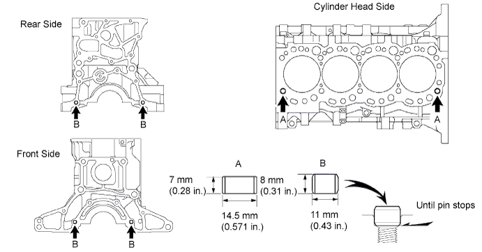
INSTALL TIGHT PLUG
-
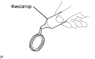
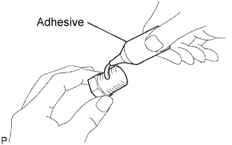
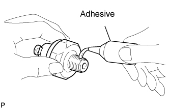
Apply adhesive to a new tight plug.
Adhesive Toyota Genuine Adhesive 1324, Three Bond 1324 or equivalent Note
Do not start the engine for 1 hour after the installation.
-
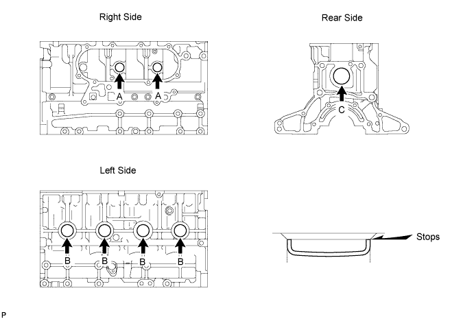
Using SST and a hammer, tap in the 2 tight plugs A.
- SST
- 09950-60010 ( 09951-00250 )
- 09950-70010 ( 09951-07100 )
-
Using SST and a hammer, tap in the 4 tight plugs B.
- SST
- 09950-60010 ( 09951-00350 )
- 09950-70010 ( 09951-07100 )
-
Using SST and a hammer, tap in the tight plug C.
- SST
- 09950-60010 ( 09951-00500 )
- 09950-70010 ( 09951-07100 )
-
-
INSTALL STUD BOLT
Note
If the stud bolt is deformed or the threads are damaged, replace it.
-
Install the stud bolts as shown in the illustration.
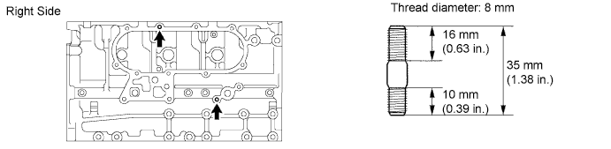
- Torque:
- 15 N*m { 150 kgf*cm, 11 ft.*lbf }
-
-
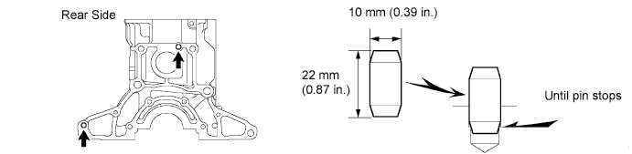
INSTALL STRAIGHT PIN
-
Install the straight pin as shown in the illustration.
-
-
INSTALL RING PIN
-
Install the ring pin as shown in the illustration.
-
-
INSTALL NO. 1 TAPER SCREW PLUG
-
Apply adhesive to 2 or 3 threads.
Adhesive Toyota Genuine Adhesive 1324, Three Bond 1324 or equivalent -
Install the screw plug.
- Torque:
- 20 N*m { 204 kgf*cm, 15 ft.*lbf }
-
-
INSTALL CYLINDER BLOCK WATER DRAIN COCK SUB-ASSEMBLY
-
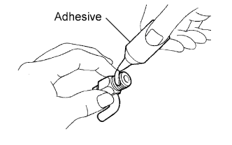
Apply adhesive to 2 or 3 threads.
Adhesive Toyota Genuine Adhesive 1324, Three Bond 1324 or equivalent -
Install the water drain cock.
- Torque:
- 57 N*m { 581 kgf*cm, 42 ft.*lbf }
Tech Tips
-
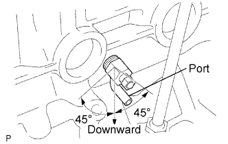
After applying the specified torque, rotate the drain union clockwise until its drain port is facing downward.
-
The drain port may be set within 45°of either side of the prescribed position.
-
-
INSTALL CRANKSHAFT POSITION SENSOR
-
Install the sensor with the bolt.
-
-
INSTALL CYLINDER BLOCK OIL ORIFICE
-
Using a 6 mm hexagon wrench, install the oil orifice.
- Torque:
- 11 N*m { 112 kgf*cm, 8 ft.*lbf }
-
-
INSTALL NO. 1 OIL NOZZLE SUB-ASSEMBLY
-
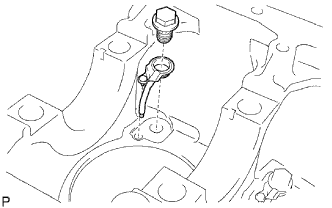
Align the pin of the oil nozzle with the pin hole of the cylinder block.
-
Install the oil nozzle with the check valve. Install the 4 oil nozzles and check valves.
- Torque:
- 25.5 N*m { 260 kgf*cm, 19 ft.*lbf }
-
-
INSTALL PISTON SUB-ASSEMBLY
-
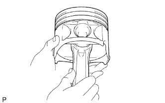
Assemble the piston and connecting rod.
-
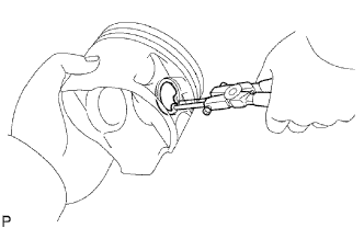
Using snap ring pliers, install a new snap ring on one side of the piston pin hole.
-
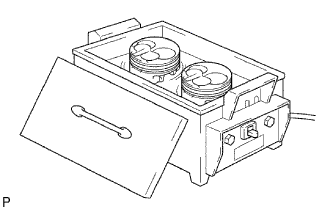
Gradually heat the piston to about 60°C (140°F).
-
Coat the piston pin with engine oil.
-
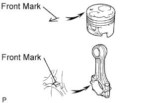
Align the front marks of the piston and connecting rod, and push in the piston pin with your thumb.
-
Check the fitting condition between the piston and piston pin. Try to move the piston back and forth on the piston pin.
-
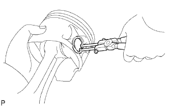
Using snap ring pliers, install a new snap ring on the other side of the piston pin hole.
-
-
Install the piston rings.
-
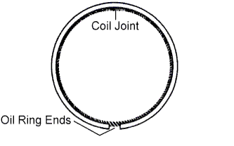
Install the coil and oil ring by hand.
Tech Tips
Face the end gap of the oil ring in the opposite direction of the coil joint.
-
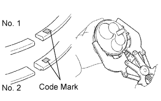
Using a piston ring expander, install the No. 1 and No. 2 piston rings with the code mark facing upward.
Code mark Item Code Mark No. 1 piston ring 1N No. 2 piston ring 2N -
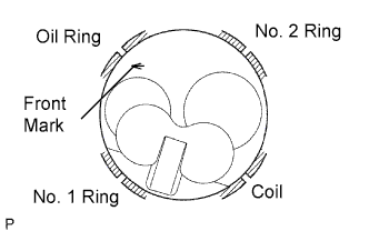
Position the piston rings so that the ring ends are as shown in the illustration.
Note
Do not align the ring ends.
-
-
-
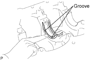
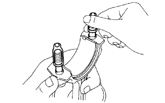
INSTALL CONNECTING ROD BEARING
-
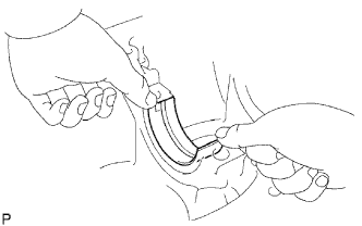
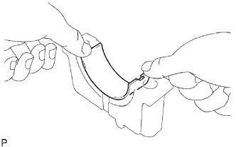
Align the bearing claw with the groove of the connecting rod or connecting rod cap.
-
Install the bearings in the connecting rod and connecting rod cap.
-
-
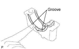
INSTALL CRANKSHAFT BEARING
Tech Tips
Upper bearings have an oil groove and oil hole; lower bearings do not.
-
Align the bearing claw with the claw groove of the cylinder block, and push in the 5 upper bearings.
-
Align the bearing claw with the claw groove of the crankshaft bearing cap, and push in the 5 lower bearings.
-
-
INSTALL CRANKSHAFT THRUST WASHER SET
-
Install the 2 thrust washers under the No. 3 journal position of the cylinder block with the oil grooves facing outward.
-
Install the 2 thrust washers on the No. 3 crankshaft bearing cap with the grooves facing outward.
-
-
INSTALL CRANKSHAFT
-
Place the crankshaft on the cylinder block.
-
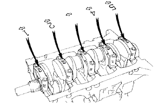
Install the 5 crankshaft bearing caps in their proper locations.
-
Install the crankshaft bearing cap bolts.
-
Apply a light coat of the engine oil to the threads and under the bolt heads of the crankshaft bearing caps.
-
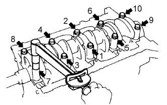
Install and uniformly tighten the 10 bolts of the crankshaft bearing caps, in several steps, in the sequence shown.
- Torque:
- 105 N*m { 1,071 kgf*cm, 77 ft.*lbf }
-
-
Check that the crankshaft turns smoothly.
-
Check the crankshaft thrust clearance Click here.
-
-
INSTALL PISTON AND CONNECTING ROD
-
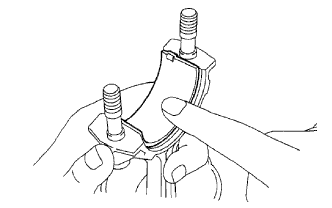
Cover the connecting rod bolts with a short piece of hose to protect the crankshaft and cylinder bore from damage.
-
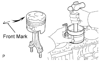
Using a piston ring compressor, push the correctly numbered piston and connecting rod assembly into the cylinder with the front mark of the piston facing forward.
-
Place the connecting rod cap on the connecting rod.
-
Match the numbered connecting rod cap with the connecting rod.
-
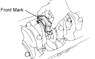
Install the connection rod cap with the front mark facing forward.
-
-
Install the connecting rod cap nuts.
Tech Tips
The connecting rod cap nuts are tightened in 2 progressive steps.
If any connecting rod bolt is broken or deformed, replace it.
-
Apply a light of engine oil to the threads and under the heads of the connecting rod cap nuts.
-
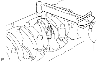
Install and alternately tighten the nuts of the connecting rod cap in several passes.
- Torque:
- 54 N*m { 551 kgf*cm, 40 ft.*lbf }
If any one of the connecting rod cap nuts does not meet the torque specification, replace them.
-
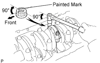
Mark the front of the connecting rod cap nuts with paint.
-
Retighten the connecting rod cap nuts 90° as shown.
-
Check that the painted mark is now at a 90° angle to the front.
-
-
Check that the crankshaft turns smoothly.
-
Check the connecting rod thrust clearance Click here.
-
-
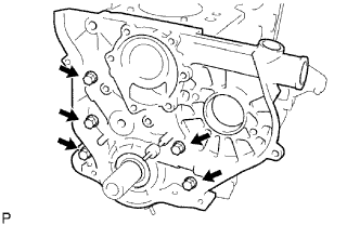
INSTALL ENGINE REAR OIL SEAL RETAINER
-
Install a new gasket and the retainer with the 4 bolts.
- Torque:
- 13 N*m { 133 kgf*cm, 10 ft.*lbf }
-
-
INSTALL TIMING GEAR CASE SUB-ASSEMBLY
-
Place a new gasket on the cylinder block.
-
Install the timing gear case with the 5 bolts.
- Torque:
- 22.5 N*m { 229 kgf*cm, 17 ft.*lbf }
-
-
INSTALL OIL STRAINER SUB-ASSEMBLY
-
Install a new gasket and oil strainer with the 2 bolts and 2 nuts.
- Torque:
- 21 N*m { 214 kgf*cm, 15 ft.*lbf, for nut }
- 18 N*m { 184 kgf*cm, 13 ft.*lbf, for bolt }
-
-
INSTALL OIL PAN SUB-ASSEMBLY
-
Remove any old packing (FIPG) material and do not drop any oil on the contact surfaces of the oil pan and cylinder block.
-
Using a gasket scraper, remove all the old packing (FIPG) material from the installation surface.
-
Thoroughly clean all components to remove all the loose material.
-
Using a non-residue solvent, clean both of the sealing surfaces.
Note
Do not use a solvent which will affect the painted surfaces.
-
-
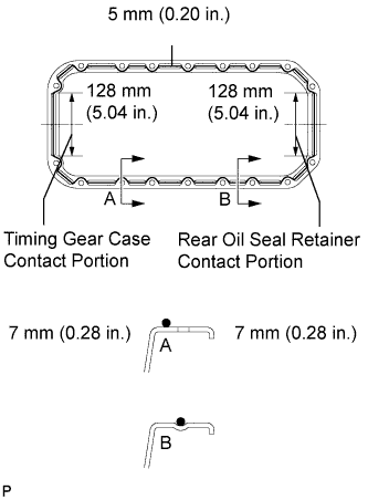
Apply seal packing to the oil pan as shown in the illustration.
Seal packing Toyota Genuine Seal Packing Black, Three Bond 1207B or equivalent Standard seal diameter 5 mm (0.20 in.) Tech Tips
-
Do not apply an excessive amount to the surface, especially near the oil passages.
-
Parts must be assembled within 5 minutes of application. Otherwise the material must be removed and reapplied.
-
After application, immediately remove the nozzle from the tube and reinstall the cap.
-
-
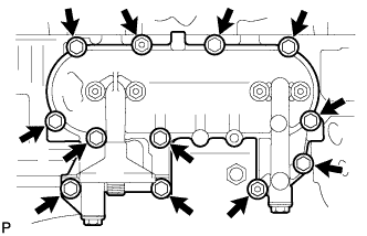
Install the oil pan with the 16 bolts and 2 nuts. Uniformly tighten the bolts and nuts in several steps.
- Torque:
- 18 N*m { 184 kgf*cm, 13 ft.*lbf }
-
-
INSTALL CRANKSHAFT TIMING PULLEY
-
Align the pulley set key with the key groove of the timing pulley.
-
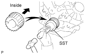
Using SST and a hammer, tap in the timing pulley, facing the flange side inward.
- SST
- 09223-46011
-
-
INSTALL WATER PUMP
-
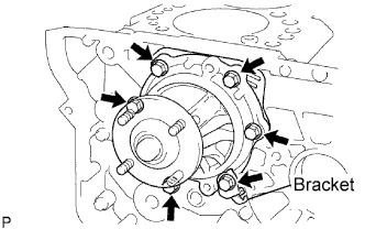
Install a new gasket, the water pump and tension spring bracket with the 6 bolts.
- Torque:
- 22.5 N*m { 229 kgf*cm, 17 ft.*lbf }
-
-
INSTALL NO. 2 TIMING BELT IDLER SUB-ASSEMBLY
-
Install the spacer and No. 2 timing belt idler with the bolt.
- Torque:
- 33 N*m { 337 kgf*cm, 24 ft.*lbf }
-
Check that the No. 2 timing belt idler moves smoothly.
-
-
INSTALL NO. 1 TIMING BELT IDLER SUB-ASSEMBLY
-
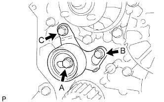
Install the No. 1 timing belt idler with the 3 bolts.
-
Tighten the bolt C.
- Torque:
- 19 N*m { 194 kgf*cm, 14 ft.*lbf, for bolt B. C }
- 44 N*m { 449 kgf*cm, 32 ft.*lbf, for bolt A }
Tech Tips
-
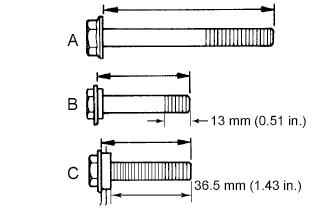
The bolt lengths for bolts A, B and C as follows.
-
Bolt C is combined with the No. 1 timing belt idler.
A 76.5 mm (3.012 in.) B 42.9 mm (1.689 in.) C 41.3 mm (1.626 in.)
-
-
INSTALL CYLINDER HEAD GASKET
-
Check the piston protrusion for each cylinder.
-
Clean the cylinder block with solvent.
-
Set the piston of the cylinder to be measured to slightly before TDC.
-
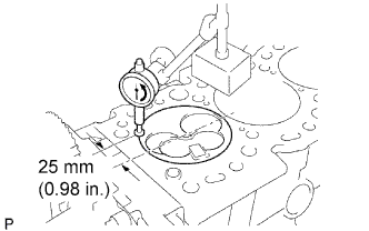
Place a dial indicator on the cylinder block, and set the measuring tip as shown in the illustration.
-
Set the dial indicator at 0 mm (0 in.).
Tech Tips
-
Use a dial indicator measuring tip as shown in the illustration.
-
Make sure that the measuring tip is square to the cylinder block gasket surface and piston head when taking the measurements.
-
-
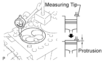
Find where the piston head protrudes most by slowly turning the crankshaft clockwise and counterclockwise.
-

Measure the protrusion of each cylinder at 2 places as shown in the illustration, making a total of 8 measurements.
-
For the piston protrusion value of each cylinder, use the average of the 2 measurements of each cylinder.
Piston protrusion 0.68 to 0.98 mm (0.0268 to 0.0386 in.) If the protrusion is not as specified, remove the piston and connecting rod assembly and reinstall it.
-
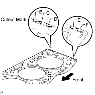
Select the largest piston protrusion value from the measurements made, then select a new appropriate gasket according to the table below.
Use gasket size Gasket Size Protrusion Use B 0.73 to 0.78 mm (0.0287 to 0.0307 in.) Use C 0.78 to 0.83 mm (0.0307 to 0.0327 in.) Use D 0.83 to 0.88 mm (0.0327 to 0.0346 in.) Use E 0.88 to 0.93 mm (0.0346 to 0.0366 in.) Use F 0.93 to 0.98 mm (0.0366 to 0.0386 in.) Tech Tips
There are 3 sizes of new cylinder head gaskets, marked B, D or F accordingly.
Cylinder head gasket thickness Cutout Mark Thickness B 1.40 to 1.50 mm (0.0551 to 0.0591 in.) C 1.45 to 1.55 mm (0.0570 to 0.0610 in.) D 1.50 to 1.60 mm (0.0591 to 0.0630 in.) E 1.55 to 1.65 mm (0.0610 to 0.0650 in.) F 1.60 to 1.70 mm (0.0630 to 0.0669 in.)
-
-
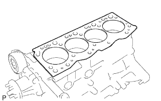
Place a new cylinder head gasket in position on the cylinder block.
Note
Be careful of the installation direction.
-
-
INSTALL CYLINDER HEAD
-
Install the cylinder head Click here.
-
-
INSTALL PUMP BRACKET
-
Install the mounting bracket with the 6 bolts.
-
-
INSTALL NO. 1 FRONT ENGINE MOUNTING BRACKET RH
-
Install the mounting bracket with the 4 bolts.
-
-
INSTALL OIL FILTER BRACKET SUB-ASSEMBLY
-
Install a new gasket and oil filter bracket with the 10 bolts and 2 nuts.
- Torque:
- 29.5 N*m { 301 kgf*cm, 22 ft.*lbf }
-
-
INSTALL OIL FILTER
-
Check and clean the oil filter installation surface.
-
Apply clean engine oil to the gasket of a new oil filter.
-
Install the oil filter, and tighten it by hand until the gasket contacts the installation surface.
-
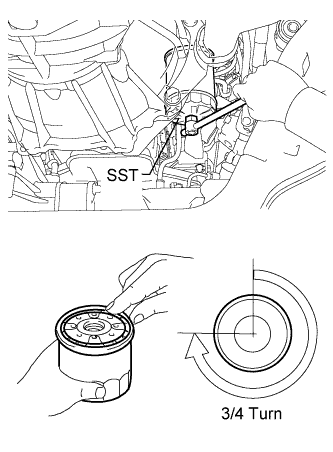
Using SST, tighten it by an additional 3/4 turn to seat the filter.
- SST
- 09228-44011
-
-
INSTALL ENGINE OIL PRESSURE SWITCH
-
Apply adhesive to 2 or 3 threads of the oil pressure switch.
Adhesive Toyota Genuine Adhesive 1344, Three Bond 1344 or equivalent -
Using a 24 mm deep socket wrench, install the oil pressure switch.
- Torque:
- 15 N*m { 153 kgf*cm, 11 ft.*lbf }
Note
Do not start the engine for at least 1 hour after installation of the switch.
-
Connect the oil pressure switch connector.
-
Start the engine and check for engine oil leaks.
-
-
INSTALL INJECTION PUMP ASSEMBLY
-
Install the injection pump to the timing gear case, and temporarily tighten the 2 nuts.
-
Install the injection pump stay to the injection pump rear end, and temporarily tighten the 3 bolts.
-
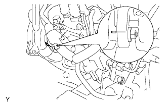
Rotate the pump body to align the marking of the pump flange and timing gear case.
-
Tighten the 2 nuts to install the injection pump.
- Torque:
- 21 N*m { 210 kgf*cm, 15 ft.*lbf }
-
Tighten the 3 bolts to install the injection pump stay.
- Torque:
- 26 N*m { 265 kgf*cm, 19 ft.*lbf, for injection pump stay to cylinder block }
- Torque:
- 26 N*m { 265 kgf*cm, 19 ft.*lbf, for injection pump stay to injection pump }
-
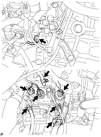
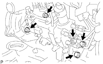
Connect the 3 fuel hoses.
-
Connect the engine speed sensor connector.
-
Connect the spill control valve connector.
-
Connect the correction unit connector.
-
Connect the timing control valve connector.
-
Connect the fuel temperature sensor connector.
-
Connect the engine wire clamp.
-
-
INSTALL INJECTION PUMP DRIVE PULLEY
-
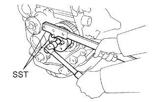
Using SST, install the injection pump drive pulley with the nut.
- SST
- 09213-14010 ( 91651-60865 )
- 09330-00021
- Torque:
- 64 N*m { 650 kgf*cm, 47 ft.*lbf }
-
-
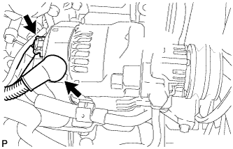
INSTALL GENERATOR WITH VACUUM PUMP ASSEMBLY
-
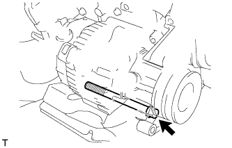
Install the generator with the bolt.
- Torque:
- 75 N*m { 765 kgf*cm, 55 ft.*lbf }
-
Connect the vacuum oil outlet hose.
-
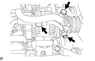
Install 2 new gaskets and the vacuum pump hose with the union bolt.
- Torque:
- 14 N*m { 143 kgf*cm, 10 ft.*lbf }
-
Install the vacuum pump oil inlet hose with 2 new gaskets and the union bolt.
- Torque:
- 14 N*m { 143 kgf*cm, 10 ft.*lbf }
-
Attach the vacuum pump oil inlet hose to the cord clip.
-
Install the generator wire with the nut.
- Torque:
- 9.8 N*m { 100 kgf*cm, 7 ft.*lbf }
-
Attach the terminal cap.
-
Connect the generator connector.
-