ELECTRONIC CONTROLLED AUTOMATIC TRANSMISSION SYSTEM (for 1KD-FTV), Diagnostic DTC:P0710, P0712, P0713
| DTC Code | DTC Name |
|---|---|
| P0710 | Transmission Fluid Temperature Sensor "A" Circuit |
| P0712 | Transmission Fluid Temperature Sensor "A" Circuit Low Input |
| P0713 | Transmission Fluid Temperature Sensor "A" Circuit High Input |
DESCRIPTION
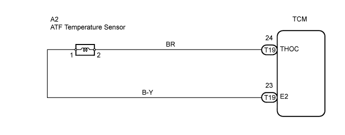
The Automatic Transmission Fluid (ATF) temperature sensor converts the ATF temperature into a resistance value which is input into the Transmission Control Module (TCM).
The TCM applies a voltage to the temperature sensor through TCM terminal THOC.
The sensor resistance changes with the ATF temperature.
One terminal of the sensor is grounded so that the sensor resistance and voltage decrease as the temperature becomes higher.
The TCM calculates the ATF based on the voltage signal.
| DTC No. | DTC Detection Condition | Trouble Area |
|---|---|---|
| P0710 |
|
|
| P0712 | ATF temperature sensor resistance is less than 79 Ω for 0.5 sec. or more (1 trip detection logic) |
|
| P0713 | ATF temperature sensor resistance is more than 156 kΩ for 15 minutes or more after the engine starts DTC is detected for 0.5 sec. or more (1 trip detection logic) |
|
MONITOR DESCRIPTION
ATF temperature sensor converts ATF temperature to an electrical resistance value. Based on the resistance, the TCM determines the ATF temperature, and the TCM detects an open or short in the ATF temperature circuit. If the resistance value of the ATF temperature is less than 79 Ω*1 or more than 156 kΩ*2, the TCM interprets this as a fault in the ATF sensor or wiring. The TCM will illuminate the MIL and store the DTC.
Tech Tips
-
*1: 150°C (302°F) or more is indicated regardless of the actual ATF temperature.
-
*2: -40°C (-40°F) is indicated regardless of the actual ATF temperature.
-
The ATF temperature can be checked on the intelligent tester display.
WIRING DIAGRAM
INSPECTION PROCEDURE
Tech Tips
Using the intelligent tester's Data List allows switch, sensor, actuator and other item values to be read without removing any parts. Reading the Data List early in troubleshooting is one way to save time.
-
Warm up the engine.
-
Turn the ignition switch OFF.
-
Connect the intelligent tester to the DLC3.
-
Turn the ignition switch ON and push the tester main switch ON.
-
Enter the following menus: Powertrain / ECT / Data List.
-
Follow the instructions on the tester and read the Data List.
| Item | Measurement Item/ Range (Display) |
Normal Condition | Diagnostic Note |
|---|---|---|---|
| A/T Oil Temperature 3 | ATF temperature sensor value/ Min.: -40°C (-40°F) Max.: 215°C (419°F) |
|
If value is -40°C (-40°F) or 215°C (419°F), ATF temperature sensor circuit is opened or short circuited |
CAUTION:
In the table above, the values listed under "Normal Condition" are reference values. Do not depend solely on these reference values when deciding whether a part is faulty or not.
Tech Tips
-
When DTC P0712 is output and the intelligent tester output is 150°C (302°F) or more, there is a short circuit.
-
When DTC P0713 is output and the intelligent tester output is -40°C (-40°F), there is an open circuit.
Measure the resistance between terminal THOC and body ground.
| Temperature Displayed | Malfunction |
|---|---|
| -40°C (-40°F) | Open circuit |
| 150°C (302°F) or more | Short circuit |
PROCEDURE
-
INSPECT ATF TEMPERATURE SENSOR
-
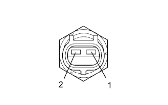
Disconnect the A2 ATF temperature sensor connector from the transmission.
-
Measure the resistance of the temperature sensor.
Standard resistance Tester Connection Specified Condition 1 - 2 79 Ω to 156 kΩ 1 - Body ground 1 MΩ or higher 2 - Body ground 1 MΩ or higher Tech Tips
If the resistance is not within the specified range for either of the ATF temperatures shown in the table below, the driveability of the vehicle may decrease.
Standard resistance ATF Temperature Specified Condition 20°C (68°F) 10.3 to 13.9 kΩ 110°C (230°F) 0.68 to 0.88 kΩ
NG 
REPLACE ATF TEMPERATURE SENSOR
OK 
-
-
CHECK WIRE HARNESS (ATF TEMPERATURE SENSOR - TCM)
-
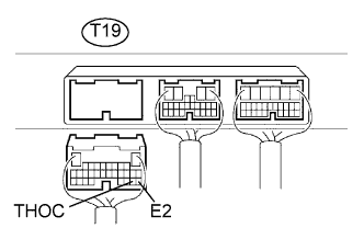
Disconnect the T19 TCM connectors.
-
Measure the resistance of the wire harness side connector.
Standard resistance Tester Connection Specified Condition T19-24 (THOC) - T19-23 (E2) 79 Ω to 156 kΩ T19-24 (THOC) - Body ground 10 kΩ or higher T19-23 (E2) - Body ground 10 kΩ or higher
NG
REPAIR OR REPLACE HARNESS AND CONNECTOR
OK 
REPLACE TCM
-