SFI SYSTEM
-
CONSTRUCTION
-
A pick-up coil type crank position sensor is used. The timing rotor of the crankshaft consists of 34 teeth with 2 teeth missing. The crank position sensor outputs the crankshaft rotation signals every 10°, and the missing teeth are used to determine the top dead center.
-
The Magnetic Resistance Element (MRE) type intake and exhaust camshaft position sensors are used. To detect the camshaft position, each timing rotor on the intake and exhaust camshafts is used to generate 3 (3 high output, 3 low output) pulses for every 2 revolutions of the crankshaft.
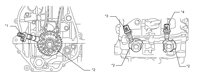
*1 Crank Position Sensor *2 Timing Rotor *3 Camshaft Position Sensor (Exhaust) *4 Camshaft Position Sensor (Intake) 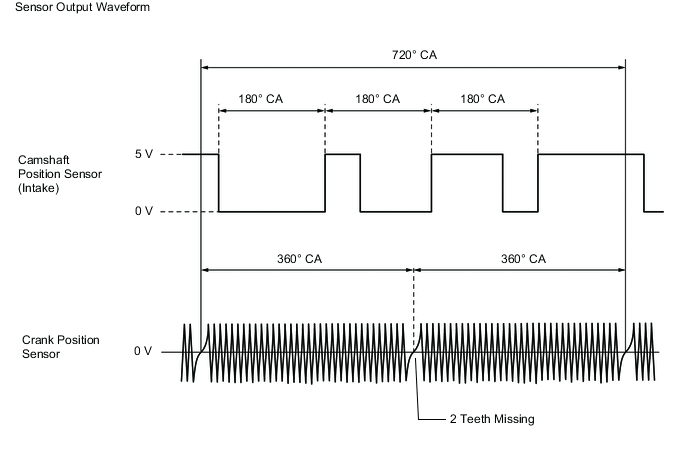
-
The MRE type camshaft position sensor consists of an MRE, a magnet and a sensor. The direction of the magnetic field changes due to the profile (protruding and non-protruding portions) of the timing rotor, which passes by the sensor. As a result, the resistance of the MRE changes, and the output voltage to the ECM changes to high or low. The ECM detects the camshaft position based on this output voltage.
-
The differences between the MRE type camshaft position sensor and the pick-up coil camshaft position sensor used on the conventional model are as follows:
Item Sensor Type MRE Pick-up Coil Signal Output Constant digital output starts from low engine speeds. Analog output changes with the engine speed. Camshaft Position Detection Detection is made by comparing the NE signals with the high/low output switch timing due to the protruded/non-protruded portions of the timing rotor, or made based on the number of the input NE signals during high/low outputs. Detection is made by comparing the NE signals with the change of waveform that is output when the protruded portion of the timing rotor passes. 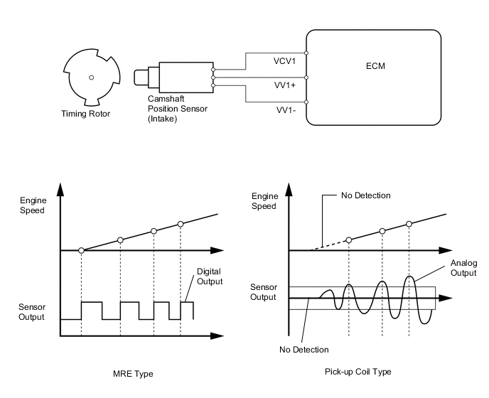
-