EXHAUST PIPE INSTALLATION
PROCEDURE
-
INSTALL AIR FUEL RATIO SENSOR (w/o Differential Pressure Sensor)
-
INSTALL FRONT EXHAUST PIPE ASSEMBLY
-
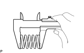
Using a vernier caliper, measure the free length of the compression spring.
Standard Length 43.0 mm (1.69 in.) Minimum Free Length 41.5 mm (1.63 in.) If the free length is less than the minimum, replace the compression spring.
-
Temporarily install a new exhaust pipe gasket to the exhaust manifold converter sub-assembly.
-
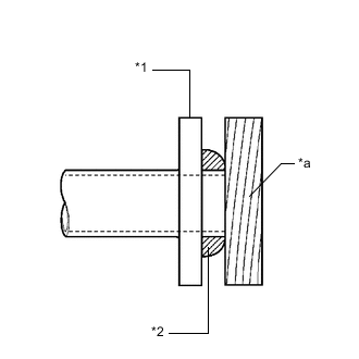
*1 Exhaust Manifold Converter Sub-assembly *2 Exhaust Pipe Gasket *a Wooden Block Using a plastic hammer and wooden block, tap in the exhaust pipe gasket until its surface is flush with the exhaust manifold converter sub-assembly.
Note
-
Be sure to install the exhaust pipe gasket in the correct direction.
-
Do not reuse the exhaust pipe gasket.
-
Do not damage the exhaust pipe gasket.
-
Do not push in the exhaust pipe gasket by using the exhaust pipe when connecting it.
-
-
Install the front exhaust pipe assembly to the exhaust manifold converter sub-assembly with the 2 compression springs and 2 bolts.
- Torque:
- 48 N*m { 489 kgf*cm, 35 ft.*lbf }
Tech Tips
After installation, check that the space between the flanges of the exhaust manifold converter sub-assembly and front exhaust pipe assembly is consistent front-to-rear and left-to-right.
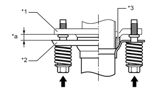
*1 Exhaust Manifold Converter Sub-assembly *2 Front Exhaust Pipe Assembly *3 Exhaust Pipe Gasket *a Space between Flanges: 8.5 mm (0.335 in.) -
w/ Canister Pump Module:
-
Engage the wire harness clamp.
-
Connect the air fuel ratio sensor connector.
-
-
-
INSTALL CENTER EXHAUST PIPE ASSEMBLY
-
Install a new exhaust pipe gasket to the front exhaust pipe assembly.
-
Connect the center exhaust pipe assembly to the 2 exhaust pipe supports.
-
Install the center exhaust pipe assembly to the front exhaust pipe assembly with the 2 nuts.
- Torque:
- 55 N*m { 561 kgf*cm, 41 ft.*lbf }
-
-
INSTALL TAIL EXHAUST PIPE ASSEMBLY
-
Using a vernier caliper, measure the free length of the compression spring.
Standard Length 43.0 mm (1.69 in.) Minimum Free Length 41.5 mm (1.63 in.) If the free length is less than the minimum, replace the compression spring.
-
Temporarily install a new exhaust pipe gasket to the center exhaust pipe assembly.
-

*1 Center Exhaust Pipe Assembly *2 Exhaust Pipe Gasket *a Wooden Block Using a plastic hammer and wooden block, tap in the exhaust pipe gasket until its surface is flush with the center exhaust pipe assembly.
Note
-
Be sure to install the exhaust pipe gasket in the correct direction.
-
Do not reuse the exhaust pipe gasket.
-
Do not damage the exhaust pipe gasket.
-
Do not push in the exhaust pipe gasket by using the exhaust pipe when connecting it.
-
-
Connect the tail exhaust pipe assembly to the 2 exhaust pipe supports.
-
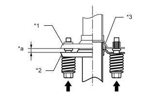
*1 Tail Exhaust Pipe Assembly *2 Center Exhaust Pipe Assembly *3 Exhaust Pipe Gasket *a Space between Flanges: 8.5 mm (0.335 in.) Install the tail exhaust pipe assembly to the center exhaust pipe assembly with the 2 compression springs and 2 bolts.
- Torque:
- 43 N*m { 438 kgf*cm, 32 ft.*lbf }
Tech Tips
After installation, check that the space between the flanges of the center exhaust pipe assembly and tail exhaust pipe assembly is consistent front-to-rear and left-to-right.
-
-
INSTALL NO. 2 TAIL EXHAUST PIPE ASSEMBLY
-
Install a new exhaust pipe gasket to the tail exhaust pipe assembly.
-
Connect the No. 2 tail exhaust pipe assembly to the 2 exhaust pipe supports.
-
Install the No. 2 tail exhaust pipe assembly to the tail exhaust pipe assembly with the 2 bolts.
- Torque:
- 55 N*m { 561 kgf*cm, 41 ft.*lbf }
-
-
INSTALL EXHAUST PIPE DAMPER
-
Install the exhaust pipe damper to the tail exhaust pipe assembly with the 2 bolts.
- Torque:
- 19 N*m { 194 kgf*cm, 14 ft.*lbf }
-
-
INSTALL HEATED OXYGEN SENSOR (for Rear Heated Oxygen Sensor)
-
INSTALL AIR FUEL RATIO SENSOR (w/ Differential Pressure Sensor)
-
INSPECT FOR EXHAUST GAS LEAK
If gas is leaking, tighten the areas necessary to stop the leak. Replace damaged parts as necessary.
-
Perform "Inspection After Repair" after repairing an exhaust gas leak.
-
for Rear Air Fuel Ratio Sensor
-
for Rear Heated Oxygen Sensor
-
-
-
PERFORM INITIALIZATION (w/ Differential Pressure Sensor)
-
Perform "Inspection After Repair" after replacing a center exhaust pipe assembly.
-