SHIFT CONTROL ACTUATOR INSTALLATION

PROCEDURE
-
INSTALL SHIFT CONTROL ACTUATOR ASSEMBLY
Note
If the shift control actuator assembly is removed, replace the shift control actuator seal.
-
Apply ATF WS around the outside edge of the case press-fit surface of the automatic transmission assembly.
-
Coat the lip of a new shift control actuator seal with a small amount of MP grease.
-
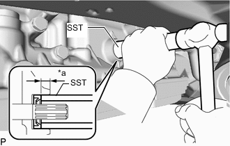
*a 6.5 to 7.3 mm (0.256 to 0.287 in.) Using SST and hammer, install the shift control actuator seal to the automatic transmission assembly.
- SST
- 09350-30020 ( 09350-07110 )
Shift Control Actuator Seal Installation Depth 6.5 to 7.3 mm (0.256 to 0.287 in.) Note
Install the shift control actuator seal so that the white marking faces the outside of the automatic transmission assembly.
-

Install the bracket to the shift control actuator assembly with the bolt.
- Torque:
- 8.0 N*m { 82 kgf*cm, 71 in.*lbf }
-
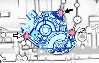

Bolt A 
Bolt B Install the shift control actuator assembly to the automatic transmission assembly with the 3 bolts.
- Torque:
- 17.5 N*m { 178 kgf*cm, 13 ft.*lbf }
Item Length Bolt A 22 mm (0.866 in.) Bolt B 40 mm (1.57 in.) Note
Clean and degrease the threads of the automatic transmission assembly side bolt holes.
Tech Tips
As the position of the shift control actuator assembly is detected automatically, initialization is not necessary after disconnecting and reconnecting the cable to the negative (-) battery terminal.
-
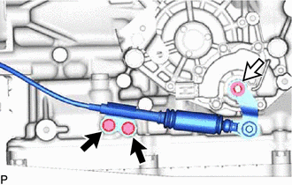
Bolt Nut and Spring Washer Connect the throttle link connecting rod assembly to the shift control actuator assembly with the nut, spring washer and 2 bolts.
- Torque:
- for bolt
- 12 N*m { 122 kgf*cm, 9 ft.*lbf }
- for nut
- 12.7 N*m { 130 kgf*cm, 9 ft.*lbf }
-

Connect the 2 connectors and attach the clamp.
-
Raise the automatic transmission assembly to a position where the engine rear mounting member bolt can be installed.
-
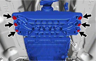
Install the 6 bolts to the engine rear mounting member.
- Torque:
- 34.7 N*m { 354 kgf*cm, 26 ft.*lbf }
-
Remove the transmission jack.
-
-
INSTALL PROPELLER WITH CENTER BEARING SHAFT ASSEMBLY