VEHICLE STABILITY CONTROL SYSTEM Crawl Indicator Light Remains ON
| DTC Code | DTC Name |
|---|---|
| Crawl Indicator Light Remains ON |
DESCRIPTION
When crawl control starts after operating the crawl switch, the crawl indicator light turns on.
WIRING DIAGRAM
Refer to Crawl Indicator Light does not Come ON (Click here).
CAUTION / NOTICE / HINT
When replacing the master cylinder solenoid, perform calibration (Click here).
PROCEDURE
READ VALUE USING INTELLIGENT TESTER (CRAWL CONTROL SWITCH)
Turn the engine switch off.
Connect the intelligent tester to the DLC3.
Turn the engine switch on (IG).
Turn the intelligent tester on.
Enter the following menus: Body Electrical / D-SEAT SW / Data List.
Body Electrical > D-SEAT SW > Data List
Tester Display
Measurement Item
Range
Normal Condition
Diagnostic Note
Crawl Control Main Switch
Crawl control switch (ON/OFF switch)
ON or OFF
ON: Crawl switch on
OFF: Crawl switch off
-
Crawl Control Up Switch
Crawl Control Switch (Speed selector switch)
ON or OFF
ON: Speed selector switch pushed to the up side and held
OFF: Speed selector switch not pushed to the up side
-
Crawl Control Down Switch
Crawl Control Switch (Speed selector switch)
ON or OFF
ON: Speed selector switch pushed to the down side and held
OFF: Speed selector switch not pushed to the down side
-
OK
The intelligent tester displays ON or OFF according to crawl control switch operation.
Result
Result
OK
NG
NG CHECK HARNESS AND CONNECTOR (CRAWL CONTROL SWITCH - DRIVING SUPPORT SWITCH CONTROL ECU)Click here
READ VALUE USING INTELLIGENT TESTER (CRAWL CONTROL LIGHT)
Turn the engine switch off.
Connect the intelligent tester to the DLC3.
Turn the engine switch on (IG).
Turn the intelligent tester on.
Enter the following menus: Chassis / ABS/VSC/TRC / Data List.
Chassis > ABS/VSC/TRC > Data List
Tester Display
Measurement Item
Range
Normal Condition
Diagnostic Note
Crawl Control Light
Crawl indicator light
ON or OFF
ON: Indicator light on
OFF: Indicator light off
-
When performing the Crawl Control Light Active Test, check Crawl Control Light in the Data List.
Chassis > ABS/VSC/TRC > Active Test
Tester Display
Measurement Item
Control Range
Diagnostic Note
Crawl Control Light
Crawl indicator light
Indicator light ON/OFF
Observe combination meter
Result
Result
Proceed to
Data List Display
Data List Display when Performing Active Test ON/OFF Operation
ON
Changes between ON and OFF
A
Does not change between ON and OFF
B
OFF
Changes between ON and OFF
A
Does not change between ON and OFF
B
CHECK HARNESS AND CONNECTOR (CRAWL CONTROL SWITCH - DRIVING SUPPORT SWITCH CONTROL ECU)
Disconnect the i5 combination switch connector.
Disconnect the G60 driving support switch control ECU connector.
Measure the resistance according to the value(s) in the table below.
Standard Resistance
Tester Connection
Condition
Specified Condition
i5-6 (ECU) - G60-15 (SWI3)
Always
Below 1 Ω
i5-6 (ECU) - Body ground
Always
10 kΩ or higher
i5-5 (UP) - G60-13 (SWI4)
Always
Below 1 Ω
i5-5 (UP) - Body ground
Always
10 kΩ or higher
i5-3 (DN) - G60-14 (SWI5)
Always
Below 1 Ω
i5-3 (DN) - Body ground
Always
10 kΩ or higher
i5-9 (E) - Body ground
Always
Below 1 Ω
Result
Result
OK
NG
NG REPAIR OR REPLACE HARNESS OR CONNECTOR
INSPECT CRAWL CONTROL SWITCH (COMBINATION SWITCH)
Remove the combination switch.
-
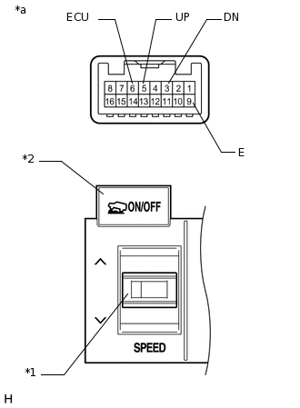
*1
Speed Selector Switch
*2
ON/OFF Switch
*a
Component without harness connected
(Crawl Control Switch [Combination Switch])
Measure the resistance according to the value(s) in the table below.
Standard Resistance
Tester Connection
Switch Condition
Specified Condition
5 (UP) - 9 (E)
SPEED (UP): Pressed
Below 1 Ω
SPEED (UP): Not Pressed
10 kΩ or higher
3 (DN) - 9 (E)
SPEED (DOWN): Pressed
Below 1 Ω
SPEED (DOWN): Not Pressed
10 kΩ or higher
6 (ECU) - 9 (E)
ON/OFF: Pressed
Below 1 Ω
ON/OFF: Not pressed
10 kΩ or higher
Result
Result
OK
NG