DYNAMIC RADAR CRUISE CONTROL SYSTEM ECU Power Source Circuit
DESCRIPTION
-
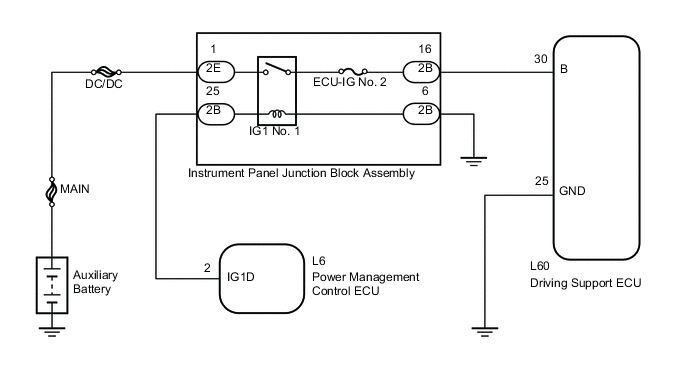
The driving support ECU assembly controls the cruise control system based on information sent from switches, sensors and ECUs.
-
The power management control ECU sends current to the IG1 No. 1 relay. This closes the contact points in the relay so that power is supplied to the driving support ECU assembly B terminal.
WIRING DIAGRAM
CAUTION / NOTICE / HINT
Note
Inspect the fuses for circuits related to this system before performing the following inspection procedure.
PROCEDURE
-
CHECK DRIVING SUPPORT ECU ASSEMBLY (B VOLTAGE)
-
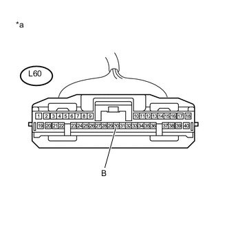
Text in Illustration *a Front view of wire harness connector
(to Driving Support ECU Assembly)
Disconnect the driving support ECU assembly connector.
-
Turn the power switch on (IG).
-
Measure the voltage according to the value(s) in the table below.
Standard Voltage Tester Connection Condition Specified Condition L60-30 (B) - Body ground Power switch on (IG) 11 to 14 V -
Reconnect the driving support ECU assembly connector.
NG 
INSPECT INSTRUMENT PANEL JUNCTION BLOCK ASSEMBLY Click here
OK 
-
-
CHECK HARNESS AND CONNECTOR (DRIVING SUPPORT ECU ASSEMBLY - BODY GROUND)
-
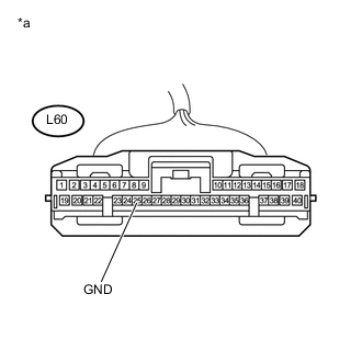
Text in Illustration *a Front view of wire harness connector
(to Driving Support ECU Assembly)
Disconnect the driving support ECU assembly connector.
-
Measure the resistance according to the value(s) in the table below.
Standard Resistance (Check for Open) Tester Connection Condition Specified Condition L60-25 (GND) - Body ground Always Below 1 Ω -
Reconnect the driving support ECU assembly connector.
OK 
PROCEED TO NEXT SUSPECTED AREA SHOWN IN PROBLEM SYMPTOMS TABLE Click here
NG
REPAIR OR REPLACE HARNESS OR CONNECTOR (DRIVING SUPPORT ECU ASSEMBLY - BODY GROUND)
-
-
INSPECT INSTRUMENT PANEL JUNCTION BLOCK ASSEMBLY
-
Remove the instrument panel junction block assembly.
-
Measure the resistance according to the value(s) in the table below.
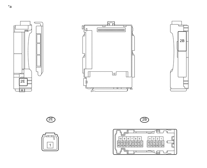
Standard Resistance Tester Connection Condition Specified Condition 2E-1 - 2B-16 Always 10 kΩ or higher 2E-1 - 2B-16 Auxiliary battery voltage applied between terminals 2B-25 and 2B-6 Below 1 Ω Text in Illustration *a Instrument Panel Junction Block Assembly - - -
Reinstall the instrument panel junction block assembly.
NG
REPLACE INSTRUMENT PANEL JUNCTION BLOCK ASSEMBLY
OK
-
-
CHECK HARNESS AND CONNECTOR (DRIVING SUPPORT ECU - INSTRUMENT PANEL JUNCTION BLOCK)
-
Disconnect the driving support ECU assembly connector.
-
Disconnect the instrument panel junction block assembly connector.
-
Measure the resistance according to the value(s) in the table below.
Standard Resistance (Check for Open) Tester Connection Condition Specified Condition L60-30 (B) - 2B-16 Always Below 1 Ω -
Reconnect the instrument panel junction block assembly connector.
-
Reconnect the driving support ECU assembly connector.
NG
REPAIR OR REPLACE HARNESS OR CONNECTOR (DRIVING SUPPORT ECU - INSTRUMENT PANEL JUNCTION BLOCK)
OK
-
-
CHECK HARNESS AND CONNECTOR (INSTRUMENT PANEL JUNCTION BLOCK ASSEMBLY - BODY GROUND)
-
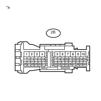
Text in Illustration *a Instrument Panel Junction Block Assembly Disconnect the instrument panel junction block assembly connector.
-
Measure the resistance according to the value(s) in the table below.
Standard Resistance (Check for Open) Tester Connection Condition Specified Condition 2B-6 - Body ground Always Below 1 Ω -
Reconnect the instrument panel junction block assembly connector.
NG
REPAIR OR REPLACE HARNESS OR CONNECTOR (INSTRUMENT PANEL JUNCTION BLOCK ASSEMBLY - BODY GROUND)
OK
-
-
CHECK HARNESS AND CONNECTOR (POWER MANAGEMENT CONTROL ECU - INSTRUMENT PANEL JUNCTION BLOCK ASSEMBLY)
-
Disconnect the power management control ECU connector.
-
Disconnect the instrument panel junction block assembly connector.
-
Measure the resistance according to the value(s) in the table below.
Standard Resistance (Check for Open) Tester Connection Condition Specified Condition 2B-25 - L6-2 (IG1D) Always Below 1 Ω Standard Resistance (Check for Short) Tester Connection Condition Specified Condition 2B-25 or L6-2 (IG1D) - Body ground Always 10 kΩ or higher -
Reconnect the power management control ECU connector.
-
Reconnect the instrument panel junction block assembly connector.
OK
REPAIR OR REPLACE HARNESS OR CONNECTOR (INSTRUMENT PANEL JUNCTION BLOCK - AUXILIARY BATTERY)
NG
REPAIR OR REPLACE HARNESS OR CONNECTOR (POWER MANAGEMENT CONTROL ECU - INSTRUMENT PANEL JUNCTION BLOCK ASSEMBLY)
-