ENGINE IMMOBILISER SYSTEM(w/o Entry and Start System), Diagnostic DTC:B279A
| DTC Code | DTC Name |
|---|---|
| B279A | Theft Deterrent System Communication Line High Fixation |
DESCRIPTION
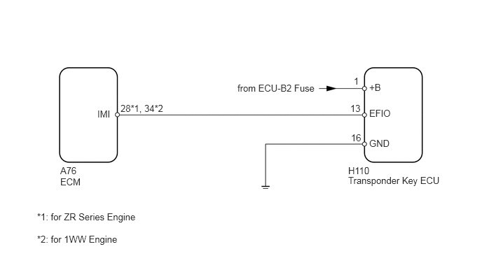
If the communication line (EFIO-IMI) to the transponder key ECU is stuck on HI output, the ECM stores this DTC.
DTC Code |
DTC Detection Condition |
Trouble Area |
|---|---|---|
B279A |
The communication line (EFIO-IMI) between the ECM and transponder key ECU is stuck on HI output for 6 seconds or more. |
|
WIRING DIAGRAM
CAUTION / NOTICE / HINT
When the transponder key ECU and/or ECM is replaced, reregister the recognition codes and ECU communication ID.
for 1WW:
After turning the ignition switch off, make sure to wait at least 6 minutes before disconnecting the ECM connector or replacing the ECM.
PROCEDURE
CLEAR DTC
Clear the DTCs (Click here).
CHECK FOR DTC
Check for DTCs (Click here).
Table 1. Result Result
Proceed to
DTC B279A is output
A
DTC B279A and other DTCs are output
B
Tip:If any DTCs other than B279A are output, troubleshoot those DTCs first.
CHECK HARNESS AND CONNECTOR (TRANSPONDER KEY ECU - ECM)
-
Disconnect the H110 ECU connector.
Disconnect the A76 ECM connector.
Measure the resistance according to the value(s) in the table below.
Standard Resistance
for ZR Series Engine
Tester Connection
Condition
Specified Condition
H110-13 (EFIO) - A76-28 (IMI)
Always
Below 1 Ω
H110-13 (EFIO) or A76-28 (IMI) - Body ground
Always
10 kΩ or higher
for 1WW Engine
Tester Connection
Condition
Specified Condition
H110-13 (EFIO) - A76-34 (IMI)
Always
Below 1 Ω
H110-13 (EFIO) or A76-34 (IMI) - Body ground
Always
10 kΩ or higher
Measure the voltage according to the value(s) in the table below.
Standard Voltage
for ZR Series Engine
Tester Connection
Condition
Specified Condition
H110-13 (EFIO) - Body ground
Always
Below 1 V
A76-28 (IMI) - Body ground
for 1WW Engine
Tester Connection
Condition
Specified Condition
H110-13 (EFIO) - Body ground
Always
Below 1 V
A76-34 (IMI) - Body ground
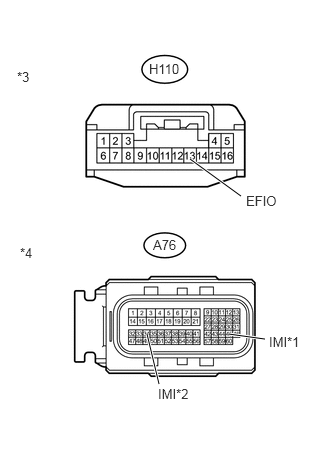
Table 2. Text in Illustration *1
for ZR Series Engine
*2
for 1WW Engine
*3
Front view of wire harness connector
(to Transponder Key ECU)
*4
Front view of wire harness connector
(to ECM)
REPAIR OR REPLACE HARNESS OR CONNECTOR
-
CHECK TRANSPONDER KEY ECU (OUTPUT)
-
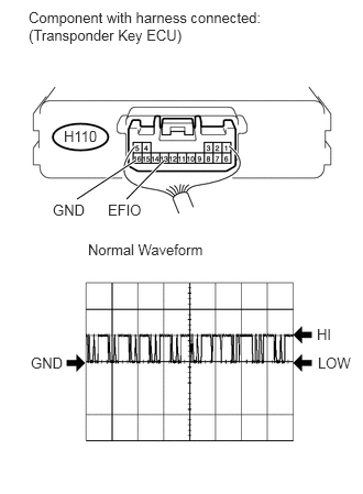
Using an oscilloscope, check the waveform.
Table 3. Measurement Condition Item
Content
Tester Connection
H110-13 (EFIO) - H110-16 (GND)
Tool Setting
10 V/DIV., 100 msec./DIV.
Condition
Ignition switch ON
OK
Waveform is output normally (refer to illustration).
Tip:If replacing the ECM, refer to the procedures below.
for 1ZR-FAE:Click here
for 2ZR-FAE:Click here
for 1WW:Click here
REPLACE ECM
-
CHECK TRANSPONDER KEY ECU (POWER SOURCE AND BODY GROUND)
-
Measure the voltage according to the value(s) in the table below.
Standard Voltage
Tester Connection
Condition
Specified Condition
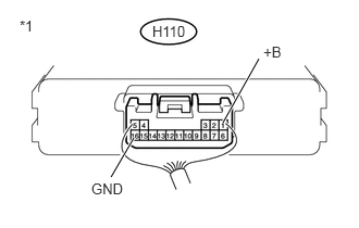
H110-1 (+B) - H110-16 (GND)
Always
11 to 14 V
Table 4. Text in Illustration *1
Component with harness connected
(Transponder Key ECU)
REPAIR OR REPLACE HARNESS OR CONNECTOR
-
REPLACE TRANSPONDER KEY ECU
Replace the transponder key ECU.
REGISTER ECU - ECM COMMUNICATION ID
Register the ECU - ECM communication ID.
CLEAR DTC
Clear the DTCs (Click here).
CHECK FOR DTC
Check for DTCs (Click here).
OK
DTC B279A is not output.
Tip:If replacing the ECM, refer to the procedures below.
for 1ZR-FAE:Click here
for 2ZR-FAE:Click here
for 1WW:Click here
END (TRANSPONDER KEY ECU IS DEFECTIVE)
REPLACE ECM