REAR DRIVE SYSTEM
-
CONSTRUCTION
-
MGR
-
A MGR has highly efficient alternating current permanent magnet motors.
-
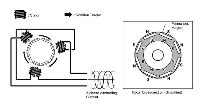
The MGR consists of a stator, stator coil, rotor, permanent magnets and a rotation sensor.
-
The MGR is provided in the rear drive unit. the MGR, which is powered by electricity from the generator (MG1) or the HV battery, drives the rear wheels in accordance with the driving conditions, achieving excellent driving stability.
-
When 3-phase alternating current is passed through the 3-phase windings of the stator coil, a rotating magnetic field is created in the electric motor. By controlling this rotating magnetic field in accordance with the rotor's rotational position and speed, the permanent magnets that are provided in the rotor become attracted by the rotating magnetic field, generating torque.
-
The generated torque is for all practical purposes proportional to the amount of current, and the rotational speed is controlled by the frequency of the alternating current.
-
Furthermore, a high level of torque, all the way to high speeds, can be generated efficiently by controlling the relationship of the rotating magnetic field to the angle of the rotor magnets.
-
When the motor is used to generate electricity, the rotation of the rotor creates a rotating magnetic field, which creates current in the phases of the stator coils.
-
-
Rotation Sensor (Resolver Type)
-
A resolver type rotation sensor is an extremely reliable and compact sensor that precisely detects the magnetic pole position. Knowing the precise position of the magnetic poles of the motor rotor is indispensable for ensuring efficient control of the MGR. The MGR has its own rotation sensor.
-
The stator of the rotation sensor contains 3 types of coils: excitation coil A, output coil S and output coil C.
-
The rotor of the rotation sensor is oval, the distance of the gap between the stator and the rotor varies with the rotation of the rotor.
-
The flow of alternating current into excitation coil A results in the creation of a constant frequency magnetic field. Using this constant frequency magnetic field, coil S and coil C will output values that correspond to the position of the rotor. Therefore, the Motor Generator ECU (MG ECU) detects the absolute position based on the difference between the coil S and coil C output values. Furthermore, the MG ECU calculates the rotational speed based on the amount of change in the position within a given length of time.
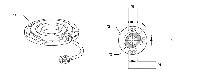
*1 Rotation Sensor (Resolver) *2 Stator *3 Rotor *4 Output Coil C *5 Output Coil S *6 Excitation Coil A -
Because the excitation coil of the rotation sensor is provided with alternating current at a constant frequency, a constant frequency magnetic field is output to coils S and C, regardless of rotor speed. The magnetic field of the excitation coil is carried to coils S and C by the rotor. The rotor is oval, and the gap between the stator of the rotation sensor and the rotor varies with the rotation of the rotor. Due to the variation of the gap, the peak values of the waveforms output by coils S and C vary in accordance with the position of the rotor.
-
The MG ECU constantly monitors these peak values, and connects them to form a virtual waveform. The MG ECU calculates the absolute position of the rotor from the difference between the values of coils S and C. It determines the rotor direction based on the difference between the phases of the virtual waveform of coil S and the virtual waveform of coil C. Furthermore, the MG ECU calculates the rotational speed based on the amount of change in the rotor position within a given length of time.
-
The diagrams below show the waveforms that are output at coils A, S and C when the rotor makes a rotation of 180°:
Figure 1. Rotation Sensor Output Waveform (Conceptual Image)
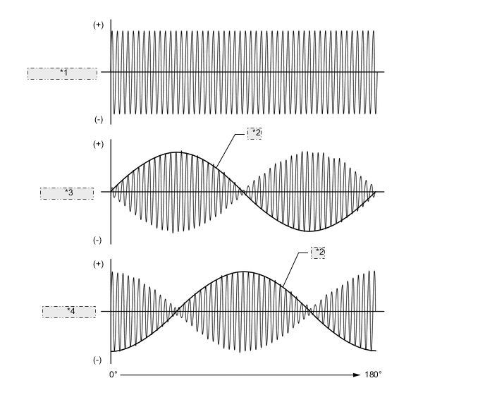
*1 Excitation Coil A *2 Theoretical Waveform *3 Output Coil S *4 Output Coil C
-
-
Temperature Sensor
-
Temperature sensor is used to detect the temperature of the stator.
-
The temperature sensor thermistor resistance changes in accordance with the change of motor temperature. The resistance of the thermistor is high when the temperature of the motor is low. Conversely, when the motor temperature is high, the thermistor resistance is low.
-
When the temperature of the motor rises, motor output is limited.
Figure 2. Characteristics of Temperature Sensor
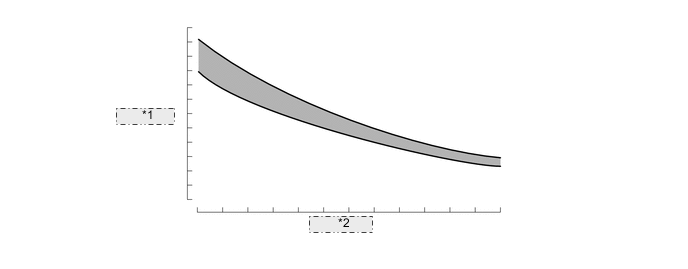
*1 Resistance *2 Temperature
-
-