POWER WINDOW CONTROL SYSTEM
-
FUNCTION OF MAIN COMPONENTS
-
The power window control system consists of the following parts:
Component Function Power Window Regulator Master Switch Assembly
-
Allows the driver to operate the power window system for the driver's door. It also allows the driver to operate the power window system for the passenger door.
-
The power window ECU in the power window regulator master switch assembly receives pulse signal from the power window regulator motor assembly and determines whether anything is caught in the window in accordance with fluctuations in that output signal.
Power Window Regulator Switch Assembly
-
Located at the passenger door, this switch assembly allows the user to operate the power window system for the passenger door.
-
The power window ECU in the power window regulator switch assembly receives pulse signal from the power window regulator motor assembly and determines whether anything is caught in the window in accordance with fluctuations in that output signal.
Power Window Regulator Motor Assembly (for Driver Side)
-
Operate when receiving motor drive signal from the applicable power window regulator master switch assembly.
-
The internal Hall IC outputs a pulse signal, and outputs it to the power window regulator master switch assembly.
Power Window Regulator Motor Assembly (for Passenger Side)
-
Operate when receiving motor drive signal from the applicable power window regulator switch assembly.
-
Operate when receiving motor drive signal from the applicable power window regulator master switch assembly.
-
The internal Hall IC outputs a pulse signal, and outputs it to the power window regulator switch assembly.
Main Body ECU (Network Gateway ECU) The IG on signal is output to the power window regulator master switch assembly via LIN communication. -
-
-
SYSTEM CONTROL
-
The power window control system has the following system control:
System Control Outline Manual-up-and-down (All Doors) The manual-up-and-down function causes the window to open or close while the power window regulator master switch assembly or power window regulator switch assembly is being pulled halfway up or pushed halfway down. The window stops as soon as the switch is released. One-touch Auto Up-and-down Function (All Doors) The one-touch auto up-and-down function enables the window to be fully opened or closed at a touch of the power window regulator master switch assembly or power window regulator switch assembly. INDEX Function If either door is opened while the door window is a nearly fully closed position, the window of the opened door will lower about 20 mm. In addition, if the door is closed, the door window will be raised to its fully closed position. Jam Protection (All Doors) The jam protection function automatically stops the power window and moves it downward if a foreign object gets jammed in the window during one-touch auto-up operation or manual-up operation. Remote Control The up-and-down operations of the passenger's door window can be controlled by operating the power window regulator master switch assembly. Window Lock Power window operation of the passenger's window is disabled when the window lock switch is pressed. Key off Operation This function makes it possible to operate the power windows for approximately 45 seconds after the ignition switch is turned off, if either door is not opened. However, if either the driver door or front passenger door is opened within this 45 seconds, the power window operation will be disabled. Tech Tips
The ECU built into each power window regulator master switch and power window regulator switch stores the initial position of its door window. The initial position is not cleared even if battery terminals, fuses or the power window motor connector is disconnected. However, after removing or reinstalling window components, or replacing the power window regulator sub-assembly or power window regulator motor assembly, the stored initial position data must be cleared and/or initialization must be performed. For details, refer to the Repair Manual.
-
Jam Protection Function
-
The jam protection function automatically stops the power window and moves it downward if a foreign object gets jammed in the door window during one-touch auto up operation or manual up operation.
-
If the window position from the full close position (amount it is open) is less than approximately 200 mm (7.9 in.) after the window has moved downward by approximately 50 mm (2.0 in.), the jam protection further moves the power window downward until the amount of open reaches approximately 200 mm (7.9 in.) or approximately 10 seconds have elapsed. However, if the power window is fully opened before the power window moves downward by approximately 50 mm (2.0 in.), this function stops.
-
Switch signal inputs for manual up-and-down and auto up-and-down operations are prohibited while the jam protection is moving the power window downward. The switch signal inputs are permitted after the jam protection operation is completed.
-
The magnet and Hall IC in the power window motor assembly are used to enable power window jam protection.
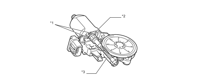
Text in Illustration *1 Hall IC *2 Magnet (for rotation detection) *3 Worm Gear - - -
The Hall IC converts the changes in the magnetic flux that occur through the rotation of the magnet into pulse signals and outputs them to the power window ECU built into each power window regulator master switch assembly and power window regulator switch assembly.
-
To control the jam protection function, the ECU determines the amount of movement and jamming of the window glass based on the pulse signals from the Hall IC.
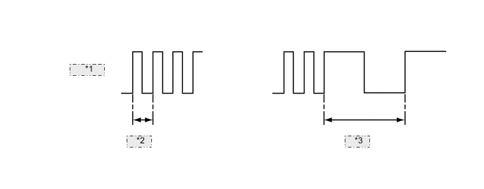
Judgment of Movement and Jamming *1 Hall IC Signal *2 Normal *3 Jammed
-
-
-
FAIL-SAFE
-
If the Hall IC in the power window motor malfunctions, the some power window functions will be prohibited for the fail-safe mode. Each power window operates when the corresponding power window switch is fully pushed down or pulled up and held in that position.
-
-
DIAGNOSIS
-
When the power window ECU detects that there is an abnormality in the Hall IC which detects the position, speed and direction of the window, the ECU enters fail-safe mode.
-