SFI SYSTEM, Diagnostic DTC:P0136,P0137,P0138 and P0139
| DTC Code | DTC Name |
|---|---|
| P0136 | O2 Sensor Circuit Bank 1 Sensor 2 |
| P0137 | O2 Sensor Circuit Low Voltage Bank 1 Sensor 2 |
| P0138 | O2 Sensor Circuit High Voltage Bank 1 Sensor 2 |
| P0139 | O2 Sensor Circuit Slow Response Bank 1 Sensor 2 |
DESCRIPTION
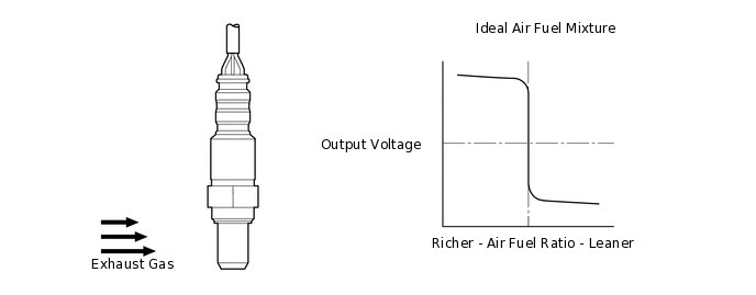
In order to obtain a high purification rate of the carbon monoxide (CO), hydrocarbon (HC) and nitrogen oxide (NOx) components in the exhaust gas, a three-way catalytic converter is used. For the most efficient use of the three-way catalytic converter, the air fuel ratio must be precisely controlled so that it is always close to the stoichiometric air fuel level. For the purpose of helping the ECM to deliver accurate air fuel ratio control, a heated oxygen sensor (sensor 2) is used. The heated oxygen sensor (sensor 2) is located behind the three-way catalytic converter, and detects the oxygen concentration in the exhaust gas. Since the sensor is integrated with the heater that heats the sensing portion, it is possible to detect the oxygen concentration even when the intake air volume is low (the exhaust gas temperature is low).
When the air fuel ratio becomes lean, the oxygen concentration in the exhaust gas is rich. The heated oxygen sensor (sensor 2) indicates to the ECM that the post-three-way catalytic converter air fuel ratio is lean (low voltage, i.e. less than 0.45 V). Conversely, when the air fuel ratio is richer than the stoichiometric air fuel level, the oxygen concentration in the exhaust gas becomes lean. The heated oxygen sensor (sensor 2) indicates to the ECM that the post-three-way catalytic converter air fuel ratio is rich (high voltage, i.e. more than 0.45 V). The heated oxygen sensor (sensor 2) has the property of changing its output voltage drastically when the air fuel ratio is close to the stoichiometric level. The ECM uses the supplementary information from the heated oxygen sensor (sensor 2) to determine whether the air fuel ratio after the three-way catalytic converter is rich or lean, and adjusts the fuel injection time accordingly. Thus, if the heated oxygen sensor (sensor 2) is working improperly due to internal malfunctions, the ECM is unable to compensate for deviations in the primary air fuel ratio control.
DTC No. |
Detection Item |
DTC Detection Condition |
Trouble Area |
MIL |
Memory |
|---|---|---|---|---|---|
P0136 |
O2 Sensor Circuit Bank 1 Sensor 2 |
Open in heated oxygen sensor (sensor 2) circuit. |
|
Comes on |
DTC stored |
P0137 |
O2 Sensor Circuit Low Voltage Bank 1 Sensor 2 |
Short to ground in heated oxygen sensor (sensor 2) circuit. |
|
Comes on |
DTC stored |
P0138 |
O2 Sensor Circuit High Voltage Bank 1 Sensor 2 |
Short to +B in heated oxygen sensor (sensor 2) circuit. |
|
Comes on |
DTC stored |
P0139 |
O2 Sensor Circuit Slow Response Bank 1 Sensor 2 |
Heated oxygen sensor (sensor 2) information and heated oxygen sensor (sensor 1) information do not match. |
|
Does not come on |
DTC stored |
MONITOR DESCRIPTION
These DTCs are stored when the heated oxygen sensor (sensor 2) output voltage is abnormal. If there is an open or short in the heated oxygen sensor (sensor 2) circuit or the heated oxygen sensor (sensor 2) output voltage is outside of the threshold, the ECM will store a DTC.
WIRING DIAGRAM
Refer to DTC P0031.
CAUTION / NOTICE / HINT
Sensor 1 refers to the sensor closest to the engine assembly.
Sensor 2 refers to the sensor farthest away from the engine assembly.
PROCEDURE
CHECK ANY OTHER DTC OUTPUT (IN ADDITION TO DTC P0136, P0137, P0138 AND/OR P0139)
Connect the GTS to the DLC3.
Turn the ignition switch to ON.
Turn the GTS on.
Enter the following menus: Powertrain / Engine / Trouble Codes.
Check for DTCs.
Powertrain > Engine > Trouble Codes
Result
Result
Proceed to
DTC P0136, P0137, P0138 and/or P0139 are output
A
DTC P0136, P0137, P0138 and/or P0139 and other DTCs are output
B
Tip:If any DTCs other than DTC P0136, P0137, P0138 or P0139 are output, troubleshoot those DTCs first.
CONFIRM IF VEHICLE HAS RUN OUT OF FUEL IN PAST
Has the vehicle run out of fuel in the past?
Result
Proceed to
YES
NO
YES DTC CAUSED BY RUNNING OUT OF FUEL
CHECK FOR EXHAUST GAS LEAK
Check the exhaust gas leaks.
OK
No gas leaks.
Result
Proceed to
OK
NG
NG REPAIR OR REPLACE EXHAUST GAS LEAK POINT
INSPECT HEATED OXYGEN SENSOR (SENSOR 2)
Inspect the heated oxygen sensor (sensor 2).
Result
Proceed to
OK
NG
CHECK HARNESS AND CONNECTOR (HEATED OXYGEN SENSOR (SENSOR 2) - ECM)
Disconnect the heated oxygen sensor (sensor 2) connector.
Disconnect the ECM connector.
Measure the resistance according to the value(s) in the table below.
Standard Resistance
Tester Connection
Condition
Specified Condition
B52-2 (HT1B) - B55-4 (HT1B)
Always
Below 1 Ω
B52-3 (EX1B) - B55-21 (EX1B)
Always
Below 1 Ω
B52-4 (OX1B) - B55-9 (OX1B)
Always
Below 1 Ω
B52-2 (HT1B) or B55-4 (HT1B) - Body ground and other terminals
Always
10 kΩ or higher
B52-3 (EX1B) or B55-21 (EX1B) - Body ground and other terminals
Always
10 kΩ or higher
B52-4 (OX1B) or B55-9 (OX1B) - Body ground and other terminals
Always
10 kΩ or higher
Result
Proceed to
OK
NG
NG REPAIR OR REPLACE HARNESS OR CONNECTOR
INSPECT HEATED OXYGEN SENSOR (SENSOR 2)
Check the heated oxygen sensor (sensor 2) installation condition.
OK
Heated oxygen sensor (sensor 2) is installed correctly.
Result
Proceed to
OK
NG
READ VALUE USING GTS (DOWNSTREAM PROBE O2 VOLTAGE)
Connect the GTS to the DLC3.
Start the engine and warm it up.
Turn the GTS on.
Enter the following menus: Powertrain / Engine / Data List / Engine Regime and Downstream Probe O2 Voltage.
Powertrain > Engine > Data List
Tester Display
Engine Regime
Downstream Probe 02 Voltage
According to the display on the GTS, read the Data List item Downstream Probe O2 Voltage while maintaining the engine speed at 2000 rpm (without load) for 120 seconds.
OK
The value alternates between the minimum (0 to 350 mV) and maximum (600 to 1000 mV).
Result
Proceed to
OK
NG
REPLACE HEATED OXYGEN SENSOR (SENSOR 2)
Replace the heated oxygen sensor (sensor 2).
Result
Proceed to
NEXT
CHECK WHETHER DTC OUTPUT RECURS (DTC P0136, P0137, P0138 AND/OR P0139)
Connect the GTS to the DLC3.
Turn the ignition switch to ON.
Turn the GTS on.
Clear the DTCs.
Powertrain > Engine > Clear DTCs
Turn the ignition switch off and wait for a few minutes.
Perform the drive test.
Turn the GTS on.
Enter the following menus: Powertrain / Engine / Trouble Codes.
Check for DTCs.
Powertrain > Engine > Trouble Codes
Result
Result
Proceed to
DTC P0136, P0137, P0138 and/or P0139 is output
A
DTCs are not output
B
B END