WIPER AND WASHER SYSTEM(w/ Rain Sensor) Front Wiper Motor Circuit
| DTC Code | DTC Name |
|---|---|
| Front Wiper Motor Circuit |
DESCRIPTION
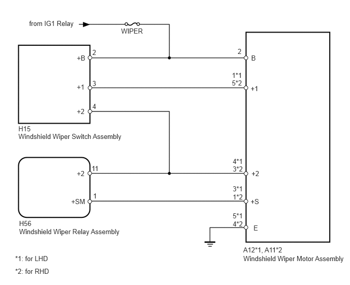
The windshield wiper relay assembly controls the windshield wiper motor assembly.
WIRING DIAGRAM
CAUTION / NOTICE / HINT
Inspect the fuses for circuits related to this system before performing the following inspection procedure.
PROCEDURE
CHECK HARNESS AND CONNECTOR (FRONT WIPER MOTOR - BATTERY)
-
Disconnect the A12*1 or A11*2 motor connector.
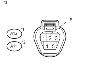
*1: for LHD
*2: for RHD
Measure the voltage according to the value(s) in the table below.
Standard Voltage
for LHD
Tester Connection
Switch Condition
Specified Condition
A12-2 (B) - Body ground
Ignition switch ON
11 to 14 V
A12-2 (B) - Body ground
Ignition switch off
Below 1 V
for RHD
Tester Connection
Switch Condition
Specified Condition
A11-2 (B) - Body ground
Ignition switch ON
11 to 14 V
A11-2 (B) - Body ground
Ignition switch off
Below 1 V
Table 1. Text in Illustration *1
for LHD
*2
for RHD
*3
Front view of wire harness connector
(to Windshield Wiper Motor Assembly)
REPAIR OR REPLACE HARNESS OR CONNECTOR
-
INSPECT WINDSHIELD WIPER MOTOR ASSEMBLY
-
Remove the windshield wiper motor assembly (Click here).
Apply battery voltage to the front wiper motor and check the speed of the front wiper motor.
OK
for LHD
Measurement Condition
Specified Condition
Battery positive (+) → Terminal 1
Battery negative (-) → Terminal 5
Motor operates at low speed
Battery positive (+) → Terminal 4
Battery negative (-) → Terminal 5
Motor operates at high speed
for RHD
Measurement Condition
Specified Condition
Battery positive (+) → Terminal 5
Battery negative (-) → Terminal 4
Motor operates at low speed
Battery positive (+) → Terminal 3
Battery negative (-) → Terminal 4
Motor operates at high speed
-
CHECK HARNESS AND CONNECTOR (FRONT WIPER MOTOR - WINDSHIELD WIPER SWITCH AND BODY GROUND)
Disconnect the A12*1 or A11*2 motor connector.
*1: for LHD
*2: for RHD
Disconnect the H15 switch connector.
Measure the resistance according to the value(s) in the table below.
Standard Resistance
for LHD
Tester Connection
Condition
Specified Condition
A12-2 (B) - H15-2 (+B)
Always
Below 1 Ω
A12-1 (+1) - H15-3 (+1)
A12-4 (+2) - H15-4 (+2)
A12-5 (E) - Body ground
A12-2 (B) - Body ground
Always
10 kΩ or higher
A12-1 (+1) - Body ground
for RHD
Tester Connection
Condition
Specified Condition
A11-2 (B) - H15-2 (+B)
Always
Below 1 Ω
A11-5 (+1) - H15-3 (+1)
A11-3 (+2) - H15-4 (+2)
A11-4 (E) - Body ground
A11-2 (B) - Body ground
Always
10 kΩ or higher
A11-5 (+1) - Body ground
Table 2. Text in Illustration *1
for LHD
*2
for RHD
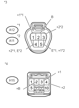
*3
Front view of wire harness connector
(to Windshield Wiper Motor Assembly)
*4
Front view of wire harness connector
(to Windshield Wiper Switch Assembly)
REPAIR OR REPLACE HARNESS OR CONNECTOR
CHECK HARNESS AND CONNECTOR (FRONT WIPER MOTOR - WINDSHIELD WIPER RELAY)
Disconnect the A12*1 or A11*2 motor connector.
*1: for LHD
*2: for RHD
Disconnect the H56 relay connector.
Measure the resistance according to the value(s) in the table below.
Standard Resistance
for LHD
Tester Connection
Condition
Specified Condition
A12-4 (+2) - H56-11 (+2)
Always
Below 1 Ω
A12-3 (+S) - H56-1 (+SM)
A12-4 (+2) - Body ground
Always
10 kΩ or higher
A12-3 (+S) - Body ground
for RHD
Tester Connection
Condition
Specified Condition
A11-3 (+2) - H56-11 (+2)
Always
Below 1 Ω
A11-1 (+S) - H56-1 (+SM)
A11-3 (+2) - Body ground
Always
10 kΩ or higher
A11-1 (+S) - Body ground
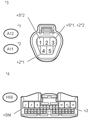
Table 3. Text in Illustration *1
for LHD
*2
for RHD
*3
Front view of wire harness connector
(to Windshield Wiper Motor Assembly)
*4
Front view of wire harness connector
(to Windshield Wiper Relay Assembly)
REPAIR OR REPLACE HARNESS OR CONNECTOR