LIGHTING SYSTEM Door Courtesy Switch Circuit
| DTC Code | DTC Name |
|---|---|
| Door Courtesy Switch Circuit |
DESCRIPTION
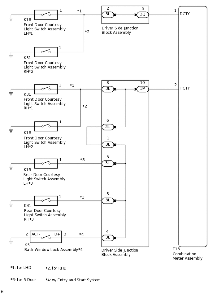
The combination meter assembly detects the condition of the front door courtesy light switch assemblies, rear door courtesy light switch assemblies*1 and back window lock assembly*2.
*1: for 5-Door
*2: w/ Entry and Start System
WIRING DIAGRAM
PROCEDURE
READ VALUE USING GTS
Connect the GTS to the DLC3.
Turn the ignition switch to ON.
Turn the GTS on.
Enter the following menus: Body Electrical / Combination Meter / Data List.
Read the Data List according to the display on the GTS.
Body Electrical > Combination Meter > Data List
Tester Display
Measurement Item
Range
Normal Condition
Diagnostic Note
Driver Side Door
Driver door courtesy light switch signal
CLOSE or OPEN
CLOSE: Driver door closed
OPEN: Driver door open
-
Door All (Except for Driver Side Seat)
Any door (except driver door) courtesy light switch signal
CLOSE or OPEN
CLOSE: Any door (except driver door) closed
OPEN: Any door (except driver door) open
-
Body Electrical > Combination Meter > Data List
Tester Display
Driver Side Door
Door All (Except for Driver Side Seat)
OK
Normal conditions listed above are displayed.
Result
Result
Proceed to
OK
A
Driver Side Door is not normal
B
Door All (Except for Driver Side Seat) is not normal
C
C INSPECT DOOR COURTESY LIGHT SWITCH ASSEMBLY OR BACK WINDOW LOCK ASSEMBLYClick here
INSPECT FRONT DOOR COURTESY LIGHT SWITCH ASSEMBLY (for Driver Side)
for LHD
Remove the front door courtesy light switch assembly LH.
Inspect the front door courtesy light switch assembly LH.
for RHD
Remove the front door courtesy light switch assembly RH.
Inspect the front door courtesy light switch assembly RH.
Result
Result
Proceed to
OK
A
NG (for LHD)
B
NG (for RHD)
C
CHECK HARNESS AND CONNECTOR (COMBINATION METER ASSEMBLY - DRIVER SIDE JUNCTION BLOCK ASSEMBLY)
Disconnect the E13 combination meter assembly connector.
Disconnect the 3Q driver side junction block assembly connector.
Measure the resistance according to the value(s) in the table below.
Standard Resistance
Tester Connection
Condition
Specified Condition
E13-1 (DCTY) - 3Q-5
Always
Below 1 Ω
E13-1 (DCTY) or 3Q-5 - Body ground
Always
10 kΩ or higher
Result
Proceed to
OK
NG
NG REPAIR OR REPLACE HARNESS OR CONNECTOR
CHECK HARNESS AND CONNECTOR (FRONT DOOR COURTESY LIGHT SWITCH ASSEMBLY - DRIVER SIDE JUNCTION BLOCK ASSEMBLY)
Disconnect the 3L driver side junction block assembly connector.
Measure the resistance according to the value(s) in the table below.
Standard Resistance
Table 1. for LHD Tester Connection
Condition
Specified Condition
K18-1 - 3L-2
Always
Below 1 Ω
K18-1 or 3L-2 - Body ground
Always
10 kΩ or higher
Standard Resistance
Table 2. for RHD Tester Connection
Condition
Specified Condition
K31-1 - 3L-2
Always
Below 1 Ω
K31-1 or 3L-2 - Body ground
Always
10 kΩ or higher
Result
Proceed to
OK
NG
NG REPAIR OR REPLACE HARNESS OR CONNECTOR
INSPECT DRIVER SIDE JUNCTION BLOCK ASSEMBLY
Remove the driver side junction block assembly.
-
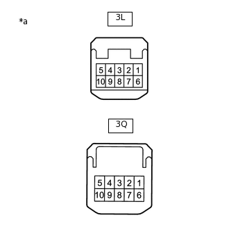
*a
Component without harness connected
(Driver Side Junction Block Assembly)
Measure the resistance according to the value(s) in the table below.
Standard Resistance
Tester Connection
Condition
Specified Condition
3Q-5 - 3L-2
Always
Below 1 Ω
Result
Proceed to
OK
NG
INSPECT DOOR COURTESY LIGHT SWITCH ASSEMBLY OR BACK WINDOW LOCK ASSEMBLY
Inspect front door courtesy light switch assembly RH (for LHD)
Remove the front door courtesy light switch assembly RH.
Inspect the front door courtesy light switch assembly RH.
Inspect front door courtesy light switch assembly LH (for RHD)
Remove the front door courtesy light switch assembly LH.
Inspect the front door courtesy light switch assembly LH.
Inspect rear door courtesy light switch assembly (for 5-Door)
Remove the rear door courtesy light switch assembly LH and rear door courtesy light switch assembly RH.
Inspect the rear door courtesy light switch assembly LH and rear door courtesy light switch assembly RH.
Inspect back window lock assembly (w/ Entry and Start System)
Remove the back window lock assembly.
Inspect the back window lock assembly.
Result
Result
Proceed to
OK
A
NG (Front door courtesy light switch assembly RH) (for LHD)
B
NG (Front door courtesy light switch assembly LH) (for RHD)
C
NG (Rear door courtesy light switch assembly LH) (for 5-Door)
D
NG (Rear door courtesy light switch assembly RH) (for 5-Door)
E
NG (Back window lock assembly) (w/ Entry and Start System)
F
CHECK HARNESS AND CONNECTOR (COMBINATION METER ASSEMBLY - DRIVER SIDE JUNCTION BLOCK ASSEMBLY)
Disconnect the E13 combination meter assembly connector.
Disconnect the 3P driver side junction block assembly connector.
Measure the resistance according to the value(s) in the table below.
Standard Resistance
Tester Connection
Condition
Specified Condition
E13-2 (PCTY) - 3P-10
Always
Below 1 Ω
E13-2 (PCTY) or 3P-10 - Body ground
Always
10 kΩ or higher
Result
Proceed to
OK
NG
NG REPAIR OR REPLACE HARNESS OR CONNECTOR
CHECK HARNESS AND CONNECTOR (FRONT DOOR COURTESY LIGHT SWITCH ASSEMBLY - DRIVER SIDE JUNCTION BLOCK ASSEMBLY)
Disconnect the 3L driver side junction block assembly connector.
Measure the resistance according to the value(s) in the table below.
Standard Resistance
Table 3. for LHD Tester Connection
Condition
Specified Condition
K31-1 - 3L-8
Always
Below 1 Ω
K31-1 or 3L-8 - Body ground
Always
10 kΩ or higher
Table 4. for RHD Tester Connection
Condition
Specified Condition
K18-1 - 3L-8
Always
Below 1 Ω
K18-1 or 3L-8 - Body ground
Always
10 kΩ or higher
Result
Proceed to
OK
NG
NG REPAIR OR REPLACE HARNESS OR CONNECTOR
CONFIRM MODEL
Choose the model to be inspected.
Result
Result
Proceed to
for 3-Door without Entry and Start System
A
for 3-Door with Entry and Start System
B
for 5-Door without Entry and Start System
C
for 5-Door with Entry and Start System
D
B CHECK HARNESS AND CONNECTOR (DRIVER SIDE JUNCTION BLOCK ASSEMBLY - DRIVER SIDE JUNCTION BLOCK ASSEMBLY)Click here
C CHECK HARNESS AND CONNECTOR (DRIVER SIDE JUNCTION BLOCK ASSEMBLY - DRIVER SIDE JUNCTION BLOCK ASSEMBLY)Click here
D CHECK HARNESS AND CONNECTOR (DRIVER SIDE JUNCTION BLOCK ASSEMBLY - DRIVER SIDE JUNCTION BLOCK ASSEMBLY)Click here
INSPECT DRIVER SIDE JUNCTION BLOCK ASSEMBLY
Remove the driver side junction block assembly.
-
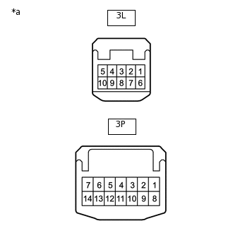
*a
Component without harness connected
(Driver Side Junction Block Assembly)
Measure the resistance according to the value(s) in the table below.
Standard Resistance
Tester Connection
Condition
Specified Condition
3P-10 - 3L-8
Always
Below 1 Ω
Result
Proceed to
OK
NG
CHECK HARNESS AND CONNECTOR (DRIVER SIDE JUNCTION BLOCK ASSEMBLY - DRIVER SIDE JUNCTION BLOCK ASSEMBLY)
Measure the resistance according to the value(s) in the table below.
Standard Resistance
Tester Connection
Condition
Specified Condition
3L-1 - 3L-6
Always
Below 1 Ω
3L-1 or 3L-6 - Body ground
Always
10 kΩ or higher
Result
Proceed to
OK
NG
NG REPAIR OR REPLACE HARNESS OR CONNECTOR
CHECK HARNESS AND CONNECTOR (BACK WINDOW LOCK ASSEMBLY - DRIVER SIDE JUNCTION BLOCK ASSEMBLY)
Measure the resistance according to the value(s) in the table below.
Standard Resistance
Tester Connection
Condition
Specified Condition
K5-3 (D+) - 3L-4
Always
Below 1 Ω
K5-3 (D+) or 3L-4 - Body ground
Always
10 kΩ or higher
K5-2 (ACT-) - Body ground
Always
Below 1 Ω
Result
Proceed to
OK
NG
NG REPAIR OR REPLACE HARNESS OR CONNECTOR
INSPECT DRIVER SIDE JUNCTION BLOCK ASSEMBLY
Remove the driver side junction block assembly.
-
*a
Component without harness connected
(Driver Side Junction Block Assembly)
Measure the resistance according to the value(s) in the table below.
Standard Resistance
Tester Connection
Condition
Specified Condition
3P-10 - 3L-6
Always
Below 1 Ω
3L-1 - 3L-4
Always
Below 1 Ω
Result
Proceed to
OK
NG
CHECK HARNESS AND CONNECTOR (DRIVER SIDE JUNCTION BLOCK ASSEMBLY - DRIVER SIDE JUNCTION BLOCK ASSEMBLY)
Measure the resistance according to the value(s) in the table below.
Standard Resistance
Tester Connection
Condition
Specified Condition
3L-1 - 3L-6
Always
Below 1 Ω
3L-1 or 3L-6 - Body ground
Always
10 kΩ or higher
Result
Proceed to
OK
NG
NG REPAIR OR REPLACE HARNESS OR CONNECTOR
CHECK HARNESS AND CONNECTOR (REAR DOOR COURTESY LIGHT SWITCH ASSEMBLY - DRIVER SIDE JUNCTION BLOCK ASSEMBLY)
Measure the resistance according to the value(s) in the table below.
Standard Resistance
Table 5. for LH side Tester Connection
Condition
Specified Condition
K15-1 - 3L-3
Always
Below 1 Ω
K15-1 or 3L-3 - Body ground
Always
10 kΩ or higher
Table 6. for RH side Tester Connection
Condition
Specified Condition
K41-1 - 3L-5
Always
Below 1 Ω
K41-1 or 3L-5 - Body ground
Always
10 kΩ or higher
Result
Proceed to
OK
NG
NG REPAIR OR REPLACE HARNESS OR CONNECTOR
INSPECT DRIVER SIDE JUNCTION BLOCK ASSEMBLY
Remove the driver side junction block assembly.
-
*a
Component without harness connected
(Driver Side Junction Block Assembly)
Measure the resistance according to the value(s) in the table below.
Standard Resistance
Tester Connection
Condition
Specified Condition
3P-10 - 3L-6
Always
Below 1 Ω
3L-1 - 3L-3
Always
Below 1 Ω
3L-1 - 3L-5
Always
Below 1 Ω
Result
Proceed to
OK
NG
CHECK HARNESS AND CONNECTOR (DRIVER SIDE JUNCTION BLOCK ASSEMBLY - DRIVER SIDE JUNCTION BLOCK ASSEMBLY)
Measure the resistance according to the value(s) in the table below.
Standard Resistance
Tester Connection
Condition
Specified Condition
3L-1 - 3L-6
Always
Below 1 Ω
3L-1 or 3L-6 - Body ground
Always
10 kΩ or higher
Result
Proceed to
OK
NG
NG REPAIR OR REPLACE HARNESS OR CONNECTOR
CHECK HARNESS AND CONNECTOR (REAR DOOR COURTESY LIGHT SWITCH ASSEMBLY - DRIVER SIDE JUNCTION BLOCK ASSEMBLY)
Measure the resistance according to the value(s) in the table below.
Standard Resistance
Table 7. for LH side Tester Connection
Condition
Specified Condition
K15-1 - 3L-3
Always
Below 1 Ω
K15-1 or 3L-3 - Body ground
Always
10 kΩ or higher
Table 8. for RH side Tester Connection
Condition
Specified Condition
K41-1 - 3L-5
Always
Below 1 Ω
K41-1 or 3L-5 - Body ground
Always
10 kΩ or higher
Result
Proceed to
OK
NG
NG REPAIR OR REPLACE HARNESS OR CONNECTOR
CHECK HARNESS AND CONNECTOR (BACK WINDOW LOCK ASSEMBLY - DRIVER SIDE JUNCTION BLOCK ASSEMBLY)
Measure the resistance according to the value(s) in the table below.
Standard Resistance
Tester Connection
Condition
Specified Condition
K5-3 (D+) - 3L-4
Always
Below 1 Ω
K5-3 (D+) or 3L-4 - Body ground
Always
10 kΩ or higher
K5-2 (ACT-) - Body ground
Always
Below 1 Ω
Result
Proceed to
OK
NG
NG REPAIR OR REPLACE HARNESS OR CONNECTOR
INSPECT DRIVER SIDE JUNCTION BLOCK ASSEMBLY
Remove the driver side junction block assembly.
-
*a
Component without harness connected
(Driver Side Junction Block Assembly)
Measure the resistance according to the value(s) in the table below.
Standard Resistance
Tester Connection
Condition
Specified Condition
3P-10 - 3L-6
Always
Below 1 Ω
3L-1 - 3L-3
Always
Below 1 Ω
3L-1 - 3L-5
Always
Below 1 Ω
3L-1 - 3L-4
Always
Below 1 Ω
Result
Proceed to
OK
NG