ENGINE UNIT REASSEMBLY
PROCEDURE
INSTALL ENGINE WATER PUMP ASSEMBLY
INSTALL OIL PUMP ASSEMBLY
INSTALL NO. 1 OIL PAN BAFFLE PLATE
Install the No. 1 oil pan baffle plate.
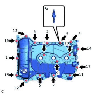
INSTALL OIL PAN SUB-ASSEMBLY
INSTALL OIL FILTER UNION
Install the oil filter union.
8.0 N*m
82 kgf*cm
71 in.*lbf
INSTALL OIL FILTER SUB-ASSEMBLY
INSTALL NO. 2 OIL PAN SUB-ASSEMBLY
INSTALL OIL PAN DRAIN PLUG
Install the oil pan drain plug and a new gasket to the oil pan sub-assembly.
42 N*m
428 kgf*cm
31 ft.*lbf
INSTALL CYLINDER HEAD GASKET
INSTALL CYLINDER HEAD SUB-ASSEMBLY
INSTALL ENGINE WATER HOUSING COVER
INSTALL ENGINE OIL PRESSURE SWITCH ASSEMBLY
INSTALL KNOCK CONTROL SENSOR
INSTALL ENGINE COOLANT TEMPERATURE SENSOR
INSTALL CAM POSITION SENSOR (for Intake Side)
INSTALL CAM POSITION SENSOR (for Exhaust Side)
INSTALL REAR CYLINDER BLOCK COVER
Clean the contact surfaces of the cylinder block sub-assembly and confirm that no oil, moisture, or other foreign matter is on the surfaces.
Using a lint free piece of cloth or paper, clean the contact surfaces of the crankshaft and let them dry.
-
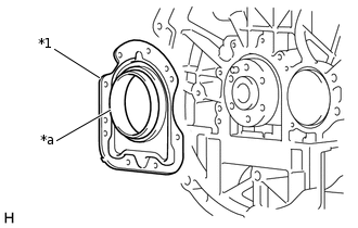
*1
Rear Cylinder Block Cover
*a
Guide Sleeve
Align the guide sleeve with the crankshaft and install a new rear cylinder block cover to the crankshaft.
Note:Do not apply engine oil to the seal ring contact surfaces.
Tip:A new rear cylinder block cover comes with a seal ring and guide sleeve.
Evenly push the rear cylinder block cover until it contacts the cylinder block, then remove the guide sleeve.
-

Install the rear cylinder block cover with the 8 bolts.
8.0 N*m
82 kgf*cm
71 in.*lbf
INSTALL NO. 1 FLYWHEEL SPACER
Install the No. 1 flywheel spacer.
INSTALL FLYWHEEL SUB-ASSEMBLY
Tip:The flywheel sub-assembly bolts are tightened in 4 progressive steps.
Step 1:
-
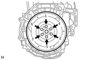
Temporarily install the flywheel sub-assembly with the 6 bolts in several steps in the sequence shown in the illustration.
8.0 N*m
82 kgf*cm
71 in.*lbf
-
Step 2:
-

Turn the crankshaft clockwise and install SST as shown in the illustration.
0109-2
0109-2B
Confirm that the crankshaft is locked and cannot be turned.
-
Step 3:
Uniformly tighten the 6 bolts in the order shown in step 1.
30 N*m
306 kgf*cm
22 ft.*lbf
-
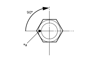
*a
Paint Mark
Step 4:
Mark each flywheel sub-assembly bolt head with paint as shown in the illustration.
Tighten the flywheel sub-assembly bolts by 90° in the order shown in step 1.
INSTALL SPEED SENSOR
INSTALL ENGINE SPEED SENSOR PROTECTOR
INSTALL TIMING BELT
INSTALL CRANKSHAFT TIMING PULLEY
Install the crankshaft timing pulley to crankshaft pulley hub.
TEMPORARILY TIGHTEN CRANKSHAFT PULLEY HUB
-
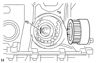
*a
Key
*b
Key Groove
Align the key of the crankshaft pulley hub with the key groove of the crankshaft, and fit the crankshaft pulley hub to the crankshaft.
-

Temporarily install the crankshaft pulley hub with bolt.
Note: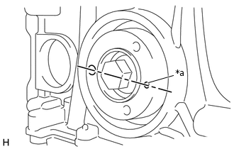
*a
Mark
Make sure the mark of the crankshaft pulley hub is horizontal as shown in the illustration.
-
INSTALL NO. 2 CAMSHAFT
INSTALL CAMSHAFT
INSTALL CAMSHAFT TIMING GEAR ASSEMBLY
INSTALL CAMSHAFT TIMING EXHAUST GEAR ASSEMBLY
INSPECT VALVE CLEARANCE
ADJUST VALVE CLEARANCE
INSTALL NO. 1 TIMING BELT IDLER SUB-ASSEMBLY
Install the No. 1 timing belt idler sub-assembly with the bolt.
20 N*m
204 kgf*cm
15 ft.*lbf
TEMPORARILY TIGHTEN TIMING BELT TENSIONER ASSEMBLY
-
*a
Hexagonal Hole of Timing Belt Tensioner Assembly
Temporarily install the timing belt tensioner assembly with the bolt.
Tip:Position the hexagonal hole of the timing belt tensioner assembly as shown in the illustration so that the timing belt tensioner assembly can be installed easily.
-
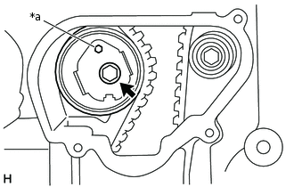
ADJUST TIMING BELT
Check the timing belt is positioned as shown in the illustration.
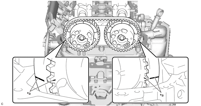
*a
Timing Mark
-
-
-
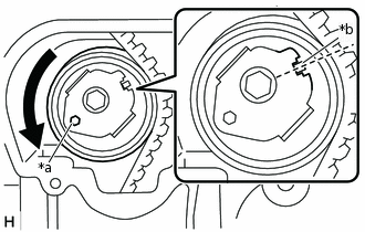
*a
Hexagonal Hole of Timing Belt Tensioner Assembly
*b
Match Mark
Insert a hexagon wrench into the hexagonal hole of the timing belt tensioner assembly and turn the timing belt tensioner assembly counterclockwise to align the match mark as shown in the illustration.
Note:Do not turn the timing belt tensioner assembly further than the match mark, or the timing belt tension may become excessive.
FULLY TIGHTEN TIMING BELT TENSIONER ASSEMBLY
Fully tighten the timing belt tensioner assembly with the bolt.
20 N*m
204 kgf*cm
15 ft.*lbf
FULLY TIGHTEN CRANKSHAFT PULLEY HUB
-
Fully tighten the crankshaft pulley hub with the bolt.
50 N*m
510 kgf*cm
37 ft.*lbf
-
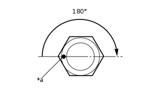
*a
Paint Mark
Mark crankshaft pulley hub bolt head with paint as shown in the illustration.
Tighten the crankshaft pulley hub bolt 180°.
-
INSTALL FUEL DELIVERY PIPE
INSTALL NO. 1 WATER BY-PASS PIPE
Install the No. 1 water by-pass pipe with the bolt.
8.0 N*m
82 kgf*cm
71 in.*lbf
INSTALL ENGINE OIL LEVEL DIPSTICK GUIDE
INSTALL CAMSHAFT TIMING OIL CONTROL VALVE ASSEMBLY (for Intake Side)
INSTALL CAMSHAFT TIMING OIL CONTROL VALVE ASSEMBLY (for Exhaust Side)
INSTALL CYLINDER BLOCK COVER
Install a new cylinder block cover gasket.
Install the cylinder block cover with the 4 bolts.
8.0 N*m
82 kgf*cm
71 in.*lbf
INSTALL CRANKSHAFT PULLEY HUB OIL SEAL
Clean the cylinder block housing and confirm that no oil, moisture, or other foreign matter is on the surfaces.
Using SST, install a new crankshaft pulley hub oil seal.
0109-3
0109-3A
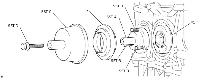
*1
Crankshaft Pulley Hub
*2
Crankshaft Pulley Hub Oil Seal
Using a screwdriver, install SST (A) with the 3 bolts (SST (B)) to the crankshaft pulley hub.
Install a new crankshaft pulley hub oil seal and SST (C) with the bolt (SST (D)).
Tighten the bolt (SST (D)) until SST (C) contacts the cylinder block.
Note:After installing the crankshaft pulley hub oil seal, wait for 30 seconds before removing SST.
INSTALL CRANKSHAFT PULLEY
Install the crankshaft pulley with the 3 bolts.
30 N*m
306 kgf*cm
22 ft.*lbf
INSTALL STUD BOLT
Tip:Perform this procedure only when replacement of the stud bolt is necessary.
-
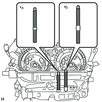
*a
Type A
*b
Type B
Using an E10 "TORX" socket wrench, install the 2 stud bolts to the cylinder head sub-assembly.
Torque
7.0 N*m (71 kgf*cm, 62 in.*lbf)
-
INSTALL CYLINDER HEAD COVER GASKET
-
Confirm that the 17 seal washer inserts are installed to the cylinder head cover sub-assembly.
-

*1
Cylinder Head Cover Gasket
Install 2 new cylinder head cover gaskets.
-
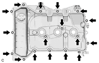
INSTALL CYLINDER HEAD COVER SUB-ASSEMBLY
-
*a
Type A
Install the cylinder head cover sub-assembly with the 17 bolts in several steps in the order shown in the illustration.
8.0 N*m
82 kgf*cm
71 in.*lbf
Tip:Using a 10 mm deep socket, tighten the bolt (type A).
-
INSTALL OIL FILLER CAP SUB-ASSEMBLY
Install the oil filler cap sub-assembly to the cylinder head cover sub-assembly.
INSTALL SPARK PLUG